Classes3 changed
Diagrams1 changed
Click a count to show only those itemspAdded — only in destinationDeleted — only in baselineMoved — same GUID, different packageChanged — same GUID and package; properties or members differIdenticalPackage (unchanged itself)struckinserted — destination text with baseline wording struck (notes, role notes, role names, multiplicities); the shows the notes and every changed propertyBlue — a changed attribute type (the new type)
▶Gridi
{21D32832-FF64-4213-B81C-55ACE35EEBFF}
Package notes
This top package includes the CIM model related to the grid.Package metadata — changes
| Baseline | Destination | |
|---|---|---|
| no changes | ||
Tagged values — changes
| Baseline | Destination | |
|---|---|---|
| no changes | ||
Package notes
This top package includes the CIM model related to the grid.▶Dynamicsi
{A71B9185-6D48-40f4-B618-485C08C4F269}
Package notes
The CIM dynamic model definitions reflect the most common IEEE or, in the case of wind models, IEC, representations of models as well as models included in some of the transient stability software widely used by utilities.
These dynamic models are intended to ensure interoperability between different vendors’ software products currently in use by electric utility energy companies, utilities, Transmission System Operators (TSOs), Regional Transmission Organizations (RTOs), and Independent System Operators (ISOs). It is important to note that each vendor is free to select its own internal implementation of these models. Differences in vendor results, as long as they are within accepted engineering practice, caused by different internal representations, are acceptable.
Unless explicitly stated otherwise, the following modelling conventions are followed:
- limited integrators are of the non-windup type;
- it shall be possible to enter a time constant of zero (where it makes sense).
The information in the entire clause "Common Information Model Dynamics package" is reproduced from the UML with the permission of UCAIug.Package metadata — changes
| Baseline | Destination | |
|---|---|---|
| no changes | ||
Tagged values — changes
| Baseline | Destination | |
|---|---|---|
| no changes | ||
Package notes
The CIM dynamic model definitions reflect the most common IEEE or, in the case of wind models, IEC, representations of models as well as models included in some of the transient stability software widely used by utilities.
These dynamic models are intended to ensure interoperability between different vendors’ software products currently in use by electric utility energy companies, utilities, Transmission System Operators (TSOs), Regional Transmission Organizations (RTOs), and Independent System Operators (ISOs). It is important to note that each vendor is free to select its own internal implementation of these models. Differences in vendor results, as long as they are within accepted engineering practice, caused by different internal representations, are acceptable.
Unless explicitly stated otherwise, the following modelling conventions are followed:
- limited integrators are of the non-windup type;
- it shall be possible to enter a time constant of zero (where it makes sense).
The information in the entire clause "Common Information Model Dynamics package" is reproduced from the UML with the permission of UCAIug.▶StandardModelsi
{1BEB429C-BFD0-49c6-9556-AC7BA58C2202}
Package notes
This subclause contains standard dynamic model specifications grouped into packages by standard function block (type of equipment being modelled).
In the CIM, standard dynamic models are expressed by means of a class named with the standard model name and attributes reflecting each of the parameters necessary to describe the behaviour of an instance of the standard model.Package metadata — changes
| Baseline | Destination | |
|---|---|---|
| no changes | ||
Tagged values — changes
| Baseline | Destination | |
|---|---|---|
| no changes | ||
Package notes
This subclause contains standard dynamic model specifications grouped into packages by standard function block (type of equipment being modelled).
In the CIM, standard dynamic models are expressed by means of a class named with the standard model name and attributes reflecting each of the parameters necessary to describe the behaviour of an instance of the standard model.▶ExcitationSystemDynamicsi
{829F67E7-F698-4aa7-95C2-13C616AB6B78}
Package notes
The excitation system model provides the field voltage (<i>Efd</i>) for a synchronous machine model. It is linked to a specific generator (synchronous machine).
The representation of all limits used by the models (not including IEEE standard models) shall comply with the representation defined in Annex E of IEEE 421.5-2005, unless specified differently in the documentation of the model.
The parameters are different for each excitation system model; the same parameter name can have different meaning in different models.Package metadata — changes
| Baseline | Destination | |
|---|---|---|
| no changes | ||
Tagged values — changes
| Baseline | Destination | |
|---|---|---|
| no changes | ||
Package notes
The excitation system model provides the field voltage (<i>Efd</i>) for a synchronous machine model. It is linked to a specific generator (synchronous machine).
The representation of all limits used by the models (not including IEEE standard models) shall comply with the representation defined in Annex E of IEEE 421.5-2005, unless specified differently in the documentation of the model.
The parameters are different for each excitation system model; the same parameter name can have different meaning in different models.Changed classes (1)
▶⚙ExcitationSystemDynamicsi
CHANGED{F119E4EC-2DC8-4801-B68B-A282AF621324}
Class notes
Excitation system function block whose behaviour is described by reference to a standard model <font color="#0f0f0f">or by definition of a user-defined model.</font>Class metadata — changes
| Baseline | Destination | |
|---|---|---|
| no changes | ||
Tagged values — changes
| Baseline | Destination | |
|---|---|---|
| no changes | ||
Class notes
Excitation system function block whose behaviour is described by reference to a standard model <font color="#0f0f0f">or by definition of a user-defined model.</font>⇄Links
ADDEDAssociation{E3C5020E-19EC-4a64-AC70-6B0F5221C5C7}
Baselinedid not exist
→
DestinationStatorCurrentLimiterDynamics role StatorCurrentLimiterDynamics [0..1] → ExcitationSystemDynamics role ExcitationSystemDynamics [1]
Link metadata
| Baseline | Destination | |
|---|---|---|
| Direction | Unspecified | |
| IsLeaf | false | |
| IsRoot | false | |
| Type | Association |
Source end
| Baseline | Destination | |
|---|---|---|
| Cardinality | 0..1 | |
| Containment | Unspecified | |
| End | Stator | |
| IsAggregation | none | |
| IsChangeable | none | |
| IsNavigable | true | |
| Ordering | false | |
| Role | Stator | |
| RoleNote | Stator current limiter model associated with this excitation system model. | |
| Scope | public | |
| TargetScope | instance |
Target end
| Baseline | Destination | |
|---|---|---|
| Cardinality | 1 | |
| Containment | Unspecified | |
| End | Excitation | |
| IsAggregation | none | |
| IsChangeable | none | |
| IsNavigable | true | |
| Ordering | false | |
| Role | Excitation | |
| RoleNote | Excitation system model with which this stator current limiter is associated. | |
| Scope | public | |
| TargetScope | instance |
Package 'ExcitationSystemDynamics' has no changes to the 39 diagrams it contains.
▶StatorCurrentLimiterDynamicsi
{224F34BE-B5D0-488c-A176-A87196201ABE}
Package notes
A stator current limiter (SCL) can be used to prevent operation that would lead to overheating of the stator winding due to high stator currents. This might happen when system voltage significantly changes or turbine power is increased without an associated upgrade of the generator stator windings. It should be mentioned that the SCL can only reduce stator current by influencing excitation during operation with reactive stator current. Alternatively a tap change of the main transformer, if applicable, or a reduction of turbine power can be considered to reduce stator current.Package metadata — changes
| Baseline | Destination | |
|---|---|---|
| no changes | ||
Tagged values — changes
| Baseline | Destination | |
|---|---|---|
| no changes | ||
Package notes
A stator current limiter (SCL) can be used to prevent operation that would lead to overheating of the stator winding due to high stator currents. This might happen when system voltage significantly changes or turbine power is increased without an associated upgrade of the generator stator windings. It should be mentioned that the SCL can only reduce stator current by influencing excitation during operation with reactive stator current. Alternatively a tap change of the main transformer, if applicable, or a reduction of turbine power can be considered to reduce stator current.Changed classes (1)
▶⚙StatorCurrentLimiterDynamicsi
CHANGED{6D1F2B33-6EEC-4bec-9185-3B3441462A9E}
Class notes
Stator current limiter whose behaviour is described by reference to a standard model <font color="#0f0f0f">or by definition of a user-defined model.</font>Class metadata — changes
| Baseline | Destination | |
|---|---|---|
| no changes | ||
Tagged values — changes
| Baseline | Destination | |
|---|---|---|
| no changes | ||
Class notes
Stator current limiter whose behaviour is described by reference to a standard model <font color="#0f0f0f">or by definition of a user-defined model.</font>⇄Links
ADDEDAssociation{E3C5020E-19EC-4a64-AC70-6B0F5221C5C7}
Baselinedid not exist
→
DestinationStatorCurrentLimiterDynamics role StatorCurrentLimiterDynamics [0..1] → ExcitationSystemDynamics role ExcitationSystemDynamics [1]
Link metadata
| Baseline | Destination | |
|---|---|---|
| Direction | Unspecified | |
| IsLeaf | false | |
| IsRoot | false | |
| Type | Association |
Source end
| Baseline | Destination | |
|---|---|---|
| Cardinality | 0..1 | |
| Containment | Unspecified | |
| End | Stator | |
| IsAggregation | none | |
| IsChangeable | none | |
| IsNavigable | true | |
| Ordering | false | |
| Role | Stator | |
| RoleNote | Stator current limiter model associated with this excitation system model. | |
| Scope | public | |
| TargetScope | instance |
Target end
| Baseline | Destination | |
|---|---|---|
| Cardinality | 1 | |
| Containment | Unspecified | |
| End | Excitation | |
| IsAggregation | none | |
| IsChangeable | none | |
| IsNavigable | true | |
| Ordering | false | |
| Role | Excitation | |
| RoleNote | Excitation system model with which this stator current limiter is associated. | |
| Scope | public | |
| TargetScope | instance |
Changed diagrams (1)
▶▦StatorCurrentLimiterDynamicsi
CHANGED{2FFE9810-34DF-4111-BB4D-BA1E76CCECD6}
Diagram notes
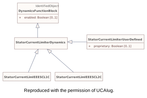
This diagram shows the dynamics model classes related to modelling of the stator current limiter models.Diagram metadata — changes
| Baseline | Destination | |
|---|---|---|
| ModifiedDate | 2022-03-18 23:04:35 | 2023-11-28 09:36:37 |
Diagram notes
This diagram shows the dynamics model classes related to modelling of the stator current limiter models.▤Metadata
| Baseline | Destination | |
|---|---|---|
| ModifiedDate | 2022-03-18 23:04:35 | 2023-11-28 09:36:37 |
▦Diagram
addedmoved or resized
Baseline
Destination
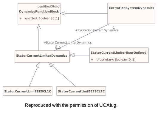
Connectors 2 addedhover a connector to outline the elements it joins
addedExcitationSystemDynamics – DynamicsFunctionBlock
addedStatorCurrentLimiterDynamics – ExcitationSystemDynamics
Package 'StandardModels' has no changes to the 2 classes it contains.
Changed classes (1)
▶⚙GridCIMVersioni
CHANGED{990AB50C-5CF8-46d2-B5FF-887BBBD3346F}
Class notes
This is the release version number assigned to Grid part of the CIM model. It is a point-in-time snapshot of the state of the CIM UML model that reflects a formal release of the CIM. This release version is distinct from the unique version (e.g. http://ucaiug.org/CIM/Base/1.0) associated with each package in the UML.Class metadata — changes
| Baseline | Destination | |
|---|---|---|
| no changes | ||
Tagged values — changes
| Baseline | Destination | |
|---|---|---|
| no changes | ||
Class notes
This is the release version number assigned to Grid part of the CIM model. It is a point-in-time snapshot of the state of the CIM UML model that reflects a formal release of the CIM. This release version is distinct from the unique version (e.g. http://ucaiug.org/CIM/Base/1.0) associated with each package in the UML.≡Attributes
| Attribute | Baseline | Destination | Notes (destination, redlined) | ||||||||||||
|---|---|---|---|---|---|---|---|---|---|---|---|---|---|---|---|
| dateimetadata changed - hovermetadata changed{8DADB97F-283D-40c7-A25A-D75E4C0D8507}show details | Date [0..1] | Date [0..1] | Form is YYYY-MM-DD for example for January 5, 2009 it is 2009-01-05. | ||||||||||||
Attribute notes Form is YYYY-MM-DD for example for January 5, 2009 it is 2009-01-05.Attribute metadata — changes
Tagged values — changes
| |||||||||||||||
| versionimetadata changed - hovermetadata changed{B4E0B1B6-8794-406a-A4C6-CBB395E37A52}show details | String [0..1] | String [0..1] | Form is XXvYY where XX is the major CIM release version and the YY is the minor version. For example 18v03. | ||||||||||||
Attribute notes Form is XXvYY where XX is the major CIM release version and the YY is the minor version. For example 18v03.Attribute metadata — changes
Tagged values — changes
| |||||||||||||||
Package 'Grid' has no changes to the 1 diagrams it contains.