Packages1 moved63 changed
Classes48 changed
Diagrams23 changed
Click a count to show only those itemspAdded — only in destinationDeleted — only in baselineMoved — same GUID, different packageChanged — same GUID and package; properties or members differIdenticalPackage (unchanged itself)struckinserted — destination text with baseline wording struck (notes, role notes, role names, multiplicities); the shows the notes and every changed propertyBlue — a changed attribute type (the new type)
▶Gridrenamed from IEC61970iTop package for IEC 61970. This top package includes the CIM model related to the grid.
CHANGED{21D32832-FF64-4213-B81C-55ACE35EEBFF}
Package notes (destination, redlined)
Package metadata — changes
| Baseline | Destination | |
|---|---|---|
| Name | IEC61970 | Grid |
Tagged values — changes
| Baseline | Destination | |
|---|---|---|
| no changes | ||
Package notes (destination, redlined)
▶BaseiContent of the base CIM published as IEC 61970-301. Content of the base CIM. The information in the entire clause "Common Information Model Base Package" is reproduced from the UML with the permission of UCAIug.
CHANGED{20A2C6D8-4765-466f-AD75-5E1B3CAF4E8D}
Package notes (destination, redlined)
Package metadata — changes
| Baseline | Destination | |
|---|---|---|
| no changes | ||
Tagged values — changes
| Baseline | Destination | |
|---|---|---|
| uri | (no tag) | http://ucaiug.org/CIM/Base/1.0 |
| version | (no tag) | 1.0.0 |
Package notes (destination, redlined)
Tagged values
| Baseline | Destination | |
|---|---|---|
| uri | (no tag) | http://ucaiug.org/CIM/Base/1.0 |
| version | (no tag) | 1.0.0 |
▶Domaini
CHANGED{0134E45C-F32A-4522-A725-E07B0AE4CB57}
Package notes
The domain package defines primitive datatypes that are used by classes in other packages. Stereotypes are used to describe the datatypes. The following stereotypes are defined:
<<enumeration>> A list of permissible constant values.
<<Primitive>> The most basic data types used to compose all other data types.
<<CIMDatatype>> A datatype that contains a value attribute, an optional unit of measure and a unit multiplier. The unit and multiplier may be specified as a static variable initialized to the allowed value.
<<Compound>> A composite of Primitive, enumeration, CIMDatatype or other Compound classes, as long as the Compound classes do not recurse.
For all datatypes both positive and negative values are allowed unless stated otherwise for a particular datatype.Package metadata — changes
| Baseline | Destination | |
|---|---|---|
| no changes | ||
Tagged values — changes
| Baseline | Destination | |
|---|---|---|
| uri | (no tag) | http://ucaiug.org/CIM/Domain/1.0 |
| version | (no tag) | 1.0.0 |
Package notes
The domain package defines primitive datatypes that are used by classes in other packages. Stereotypes are used to describe the datatypes. The following stereotypes are defined:
<<enumeration>> A list of permissible constant values.
<<Primitive>> The most basic data types used to compose all other data types.
<<CIMDatatype>> A datatype that contains a value attribute, an optional unit of measure and a unit multiplier. The unit and multiplier may be specified as a static variable initialized to the allowed value.
<<Compound>> A composite of Primitive, enumeration, CIMDatatype or other Compound classes, as long as the Compound classes do not recurse.
For all datatypes both positive and negative values are allowed unless stated otherwise for a particular datatype.Tagged values
| Baseline | Destination | |
|---|---|---|
| uri | (no tag) | http://ucaiug.org/CIM/Domain/1.0 |
| version | (no tag) | 1.0.0 |
Changed classes (1)
▶⚙Mass«CIMDatatype»i
CHANGED{3090EC66-8B19-4224-A206-00BFE70ECED0}
Class notes
Mass.Class metadata — changes
| Baseline | Destination | |
|---|---|---|
| no changes | ||
Tagged values — changes
| Baseline | Destination | |
|---|---|---|
| no changes | ||
Class notes
Mass.≡Attributes
| Attribute | Baseline | Destination | Notes (destination, redlined) | ||||||||||||
|---|---|---|---|---|---|---|---|---|---|---|---|---|---|---|---|
| multiplierimetadata changed - hovermetadata changed{D40AF86B-C0F4-411f-91D2-A75099897751}show details | UnitMultiplier [0..1] | UnitMultiplier [0..1] | |||||||||||||
Attribute notes No notes defined in the model.Attribute metadata — changes
Tagged values — changes
| |||||||||||||||
| unitimetadata changed - hovermetadata changed{6CF35055-FDC7-44dc-B75D-BD9B6175FE11}show details | UnitSymbol [0..1] | UnitSymbol [0..1] | |||||||||||||
Attribute notes No notes defined in the model.Attribute metadata — changes
Tagged values — changes
| |||||||||||||||
Changed diagrams (1)
▶▦GeneralDatatypesi
CHANGED{9478D0BE-F328-4c54-BE7D-DE95D8744E6B}
Diagram notes
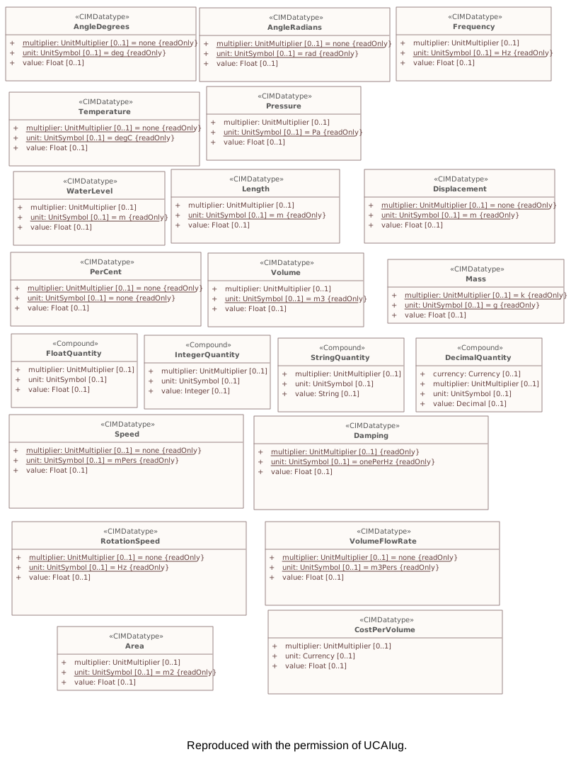
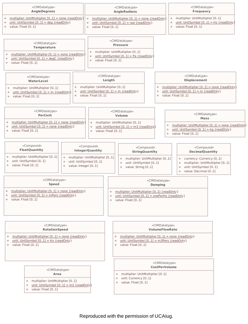
This diagram shows general data types.Diagram metadata — changes
| Baseline | Destination | |
|---|---|---|
| no changes | ||
Diagram notes
This diagram shows general data types.▦Diagram
changed
Baseline
Destination
▶Corei
CHANGED{6A503B72-6E15-4cd1-B92D-DDF6D14DBE29}
Package notes
Contains the core PowerSystemResource and ConductingEquipment entities shared by all applications plus common collections of those entities. Not all applications require all the Core entities. This package does not depend on any other package except the Domain package, but most of the other packages have associations and generalizations that depend on it.Package metadata — changes
| Baseline | Destination | |
|---|---|---|
| no changes | ||
Tagged values — changes
| Baseline | Destination | |
|---|---|---|
| uri | (no tag) | http://ucaiug.org/CIM/Core/1.0 |
| version | (no tag) | 1.0.0 |
Package notes
Contains the core PowerSystemResource and ConductingEquipment entities shared by all applications plus common collections of those entities. Not all applications require all the Core entities. This package does not depend on any other package except the Domain package, but most of the other packages have associations and generalizations that depend on it.Tagged values
| Baseline | Destination | |
|---|---|---|
| uri | (no tag) | http://ucaiug.org/CIM/Core/1.0 |
| version | (no tag) | 1.0.0 |
Changed classes (3)
▶⚙ACDCTerminali
CHANGED{D37077B9-3B0C-4c16-8F5F-9A6F2C83A7F2}
Class notes
An electrical connection point (AC or DC) to a piece of conducting equipment. Terminals are connected at physical connection points called connectivity nodes.Class metadata — changes
| Baseline | Destination | |
|---|---|---|
| no changes | ||
Tagged values — changes
| Baseline | Destination | |
|---|---|---|
| no changes | ||
Class notes
An electrical connection point (AC or DC) to a piece of conducting equipment. Terminals are connected at physical connection points called connectivity nodes.⇄Links
CHANGEDAssociation{61C72648-1B2B-4ebb-ABD7-BD93DFF34E44}
→
Source end
no changes
Target end — ACDCTerminal
| Baseline | Destination | |
|---|---|---|
| RoleNote | Th eterminal for this signal descriptor. |
▶⚙Equipmenti
CHANGED{F8DD8DAC-3545-4660-9CA5-794881CC6591}
Class notes
The parts of a power system that are physical devices, electronic or mechanical.Class metadata — changes
| Baseline | Destination | |
|---|---|---|
| no changes | ||
Tagged values — changes
| Baseline | Destination | |
|---|---|---|
| no changes | ||
Class notes
The parts of a power system that are physical devices, electronic or mechanical.≡Attributes
| Attribute | Baseline | Destination | Notes (destination, redlined) | ||||||||||||
|---|---|---|---|---|---|---|---|---|---|---|---|---|---|---|---|
| aggregatei{3C000D48-C67D-4cc3-89D6-5F336420B325}show details | Boolean [0..1] | Boolean [0..1] | The aggregate flag provides an alternative way of representing an aggregated (equivalent) element. It is applicable in cases when the dedicated classes for equivalent equipment do not have all of the attributes necessary to represent the required level of detail. In case the flag is set to “true” the single instance of equipment represents multiple pieces of equipment that have been modelled together as an aggregate equivalent obtained by a network reduction procedure. Examples would be power transformers or synchronous machines operating in parallel modelled as a single aggregate power transformer or aggregate synchronous machine.
The attribute is not used for EquivalentBranch, EquivalentShunt, EquivalentInjection and | ||||||||||||
Attribute notes (destination, redlined) The aggregate flag provides an alternative way of representing an aggregated (equivalent) element. It is applicable in cases when the dedicated classes for equivalent equipment do not have all of the attributes necessary to represent the required level of detail. In case the flag is set to “true” the single instance of equipment represents multiple pieces of equipment that have been modelled together as an aggregate equivalent obtained by a network reduction procedure. Examples would be power transformers or synchronous machines operating in parallel modelled as a single aggregate power transformer or aggregate synchronous machine.
The attribute is not used for EquivalentBranch, EquivalentShunt, EquivalentInjection and Attribute metadata — changes
Tagged values — changes
| |||||||||||||||
▶⚙PowerSystemResourcei
CHANGED{0340C084-3759-40cc-AAF2-386101DE842F}
Class notes
A power system resource (PSR) can be an item of equipment such as a switch, an equipment container containing many individual items of equipment such as a substation, or an organisational entity such as sub-control area. Power system resources can have measurements associated.Class metadata — changes
| Baseline | Destination | |
|---|---|---|
| no changes | ||
Tagged values — changes
| Baseline | Destination | |
|---|---|---|
| no changes | ||
Class notes
A power system resource (PSR) can be an item of equipment such as a switch, an equipment container containing many individual items of equipment such as a substation, or an organisational entity such as sub-control area. Power system resources can have measurements associated.⇄Links
CHANGEDAssociation{4F85BB5D-133B-4060-B422-86E5B9320EE2}
BaselineVerificationAction role VerificationAction [0..*] → PowerSystemResource role PowerSystemResource [0..1]
→
DestinationVerificationAction role VerificationAction [0..*] → PowerSystemResource role PowerSystemResource [0..1]
Source end — VerificationAction
| Baseline | Destination | |
|---|---|---|
| RoleNote | The verification action that is performed on the power system resource | The verification action that is performed on the power system resource. |
Target end — PowerSystemResource
| Baseline | Destination | |
|---|---|---|
| RoleNote | The power system resource that the verification action is performed on | The power system resource that the verification action is performed on. |
CHANGEDAssociation{7F56BF7C-C7AA-432b-8454-59AE37E0C7F8}
BaselineGenericAction role GenericAction [0..*] → PowerSystemResource role PowerSystemResource [0..1]
→
DestinationGenericAction role GenericAction [0..*] → PowerSystemResource role PowerSystemResource [0..1]
Source end — GenericAction
| Baseline | Destination | |
|---|---|---|
| RoleNote | The generic action that is performed on the power system resource | The generic action that is performed on the power system resource. |
Target end — PowerSystemResource
| Baseline | Destination | |
|---|---|---|
| RoleNote | The power system resource that the generic action is performed on | The power system resource that the generic action is performed on. |
Package 'Core' has no changes to the 7 diagrams it contains.
▶Wiresi
CHANGED{6C99E9CA-2035-4035-B77F-9217E17D86F4}
Package notes
An extension to the Core and Topology package that models information on the electrical characteristics of Transmission and Distribution networks. This package is used by network applications such as State Estimation, Load Flow and Optimal Power Flow.Package metadata — changes
| Baseline | Destination | |
|---|---|---|
| no changes | ||
Tagged values — changes
| Baseline | Destination | |
|---|---|---|
| uri | (no tag) | http://ucaiug.org/CIM/Wires/1.0 |
| version | (no tag) | 1.0.0 |
Package notes
An extension to the Core and Topology package that models information on the electrical characteristics of Transmission and Distribution networks. This package is used by network applications such as State Estimation, Load Flow and Optimal Power Flow.Tagged values
| Baseline | Destination | |
|---|---|---|
| uri | (no tag) | http://ucaiug.org/CIM/Wires/1.0 |
| version | (no tag) | 1.0.0 |
Changed classes (21)
▶⚙ACLineSegmenti
CHANGED{625BD764-3907-4d65-8497-7FD09708BD8E}
Class notes
A wire or combination of wires, with consistent electrical characteristics, building a single electrical system, used to carry alternating current between points in the power system.
For symmetrical, transposed three phase lines, it is sufficient to use attributes of the line segment, which describe impedances and admittances for the entire length of the segment. Additionally impedances can be computed by using length and associated per length impedances.
The BaseVoltage at the two ends of ACLineSegments in a Line shall have the same BaseVoltage.nominalVoltage. However, boundary lines may have slightly different BaseVoltage.nominalVoltages and variation is allowed. Larger voltage difference in general requires use of an equivalent branch.Class metadata — changes
| Baseline | Destination | |
|---|---|---|
| no changes | ||
Tagged values — changes
| Baseline | Destination | |
|---|---|---|
| no changes | ||
Class notes
A wire or combination of wires, with consistent electrical characteristics, building a single electrical system, used to carry alternating current between points in the power system.
For symmetrical, transposed three phase lines, it is sufficient to use attributes of the line segment, which describe impedances and admittances for the entire length of the segment. Additionally impedances can be computed by using length and associated per length impedances.
The BaseVoltage at the two ends of ACLineSegments in a Line shall have the same BaseVoltage.nominalVoltage. However, boundary lines may have slightly different BaseVoltage.nominalVoltages and variation is allowed. Larger voltage difference in general requires use of an equivalent branch.⇄Links
CHANGEDAssociation{F29D4402-D392-434d-9E98-8C35F21BD856}
→
Source end — ACLineSegment
| Baseline | Destination | |
|---|---|---|
| RoleNote | The AC line segment defined by the wire spacing information | The AC line segment defined by the wire spacing information. |
Target end — WireSpacingInfo
| Baseline | Destination | |
|---|---|---|
| RoleNote | The wire spacing information that applies to this AC line segment | The wire spacing information that applies to this AC line segment. |
▶⚙Clampi
CHANGED{7B0758AF-6E8E-438e-BD69-A838A56F256D}
Class notes
A Clamp is a galvanic connection at a line segment where other equipment is connected. A Clamp does not cut the line segment.
A Clamp is ConductingEquipment and has one Terminal with an associated ConnectivityNode. Any other ConductingEquipment can be connected to the Clamp ConnectivityNode.Class metadata — changes
| Baseline | Destination | |
|---|---|---|
| no changes | ||
Tagged values — changes
| Baseline | Destination | |
|---|---|---|
| no changes | ||
Class notes
A Clamp is a galvanic connection at a line segment where other equipment is connected. A Clamp does not cut the line segment.
A Clamp is ConductingEquipment and has one Terminal with an associated ConnectivityNode. Any other ConductingEquipment can be connected to the Clamp ConnectivityNode.⇄Links
CHANGEDAssociation{74C6F744-E53A-4fd0-BBA8-3531659CCC10}
→
Source end — Clamp
| Baseline | Destination | |
|---|---|---|
| RoleNote | The clamp that the clamp action is performed on | The clamp that the clamp action is performed on. |
Target end — ClampAction
| Baseline | Destination | |
|---|---|---|
| RoleNote | The clamp action that is performed on the clamp | The clamp action that is performed on the clamp. |
▶⚙EnergyConsumeri
CHANGED{BCEC7EE8-7294-4b50-8216-0286C31A035C}
Class notes
Generic user of energy - a point of consumption on the power system model.
EnergyConsumer.pfixed, .qfixed, .pfixedPct and .qfixedPct have meaning only if there is no LoadResponseCharacteristic associated with EnergyConsumer or if LoadResponseCharacteristic.exponentModel is set to False.Class metadata — changes
| Baseline | Destination | |
|---|---|---|
| no changes | ||
Tagged values — changes
| Baseline | Destination | |
|---|---|---|
| no changes | ||
Class notes
Generic user of energy - a point of consumption on the power system model.
EnergyConsumer.pfixed, .qfixed, .pfixedPct and .qfixedPct have meaning only if there is no LoadResponseCharacteristic associated with EnergyConsumer or if LoadResponseCharacteristic.exponentModel is set to False.≡Attributes
| Attribute | Baseline | Destination | Notes (destination, redlined) | ||||||||||||
|---|---|---|---|---|---|---|---|---|---|---|---|---|---|---|---|
| groundedi{56A0DAAA-8C90-4e10-B63E-47E544C63EF6}show details | Boolean [0..1] | Boolean [0..1] | |||||||||||||
Attribute notes (destination, redlined) Attribute metadata — changes
Tagged values — changes
| |||||||||||||||
⇄Links
CHANGEDAssociation{FED8229A-5B6E-4728-A961-4E85004FEA54}
BaselineEnergyConsumer role EnergyConsumer [0..1] → EnergyConsumerAction role EnergyConsumerAction [0..1]
→
DestinationEnergyConsumer role EnergyConsumer [0..1] → EnergyConsumerAction role EnergyConsumerAction [0..1]
Source end — EnergyConsumer
| Baseline | Destination | |
|---|---|---|
| RoleNote | The energy consumer that the energy consumer action is performed on | The energy consumer that the energy consumer action is performed on. |
Target end — EnergyConsumerAction
| Baseline | Destination | |
|---|---|---|
| RoleNote | The energy consumer action that is performed on the energy consumer | The energy consumer action that is performed on the energy consumer. |
▶⚙ExternalNetworkInjectioni
CHANGED{B7E110A4-CE7A-4414-9477-4310D44B43D0}
Class notes (destination, redlined)
This class represents the external network and is used for IEC 60909 calculations. It is only used if EquivalentInjection cannot provide the details required by IEC 60909 on short circuit equivalent of an external network.Class metadata — changes
| Baseline | Destination | |
|---|---|---|
| no changes | ||
Tagged values — changes
| Baseline | Destination | |
|---|---|---|
| no changes | ||
Class notes (destination, redlined)
This class represents the external network and is used for IEC 60909 calculations. It is only used if EquivalentInjection cannot provide the details required by IEC 60909 on short circuit equivalent of an external network.Class 'ExternalNetworkInjection' has no other changes. The shows its notes and every changed property.
▶⚙NonlinearShuntCompensatoriggTotal, bbTotal, g0g0Total and b0b0Total of the associated NonlinearShuntCompensatorPoint describe the total conductance and admittance of a NonlinearShuntCompensatorPoint at a section number specified by NonlinearShuntCompensatorPoint.sectionNumber.
CHANGED{111DB4FF-7967-4eb5-AABE-CDA0EA065CF8}
Class notes (destination, redlined)
A non linear shunt compensator has bank or section admittance values that differ. The attributes Class metadata — changes
| Baseline | Destination | |
|---|---|---|
| no changes | ||
Tagged values — changes
| Baseline | Destination | |
|---|---|---|
| no changes | ||
Class notes (destination, redlined)
A non linear shunt compensator has bank or section admittance values that differ. The attributes Class 'NonlinearShuntCompensator' has no other changes. The shows its notes and every changed property.
▶⚙NonlinearShuntCompensatorPhaseiggTotal and bbTotal of the associated NonlinearShuntCompensatorPhasePoint describe the total conductance and admittance of a NonlinearShuntCompensatorPhasePoint at a section number specified by NonlinearShuntCompensatorPhasePoint.sectionNumber.
CHANGED{178D630D-8883-41d1-BFE0-81BFD2B70087}
Class notes (destination, redlined)
A per phase non linear shunt compensator has bank or section admittance values that differ. The attributes Class metadata — changes
| Baseline | Destination | |
|---|---|---|
| no changes | ||
Tagged values — changes
| Baseline | Destination | |
|---|---|---|
| no changes | ||
Class notes (destination, redlined)
A per phase non linear shunt compensator has bank or section admittance values that differ. The attributes Class 'NonlinearShuntCompensatorPhase' has no other changes. The shows its notes and every changed property.
▶⚙NonlinearShuntCompensatorPhasePointiNonlinearShuntCompenstorPhasePointNonlinearShuntCompensatorPhasePoint instances associated with a NonlinearShuntCompensatorPhase shall be equal to ShuntCompensatorPhase.maximumSections. ShuntCompensator.sections shall only be set to one of the NonlinearShuntCompenstorPhasePointNonlinearShuntCompensatorPhasePoint.sectionNumber. There is no interpolation between NonlinearShuntCompenstorPhasePointNonlinearShuntCompensatorPhasePoint-s.
CHANGED{44BDEBB6-4580-4df6-9245-179240EB5058}
Class notes (destination, redlined)
A per phase non linear shunt compensator bank or section admittance value. The number of Class metadata — changes
| Baseline | Destination | |
|---|---|---|
| no changes | ||
Tagged values — changes
| Baseline | Destination | |
|---|---|---|
| no changes | ||
Class notes (destination, redlined)
A per phase non linear shunt compensator bank or section admittance value. The number of ≡Attributes
| Attribute | Baseline | Destination | Notes (destination, redlined) | ||||||||||||
|---|---|---|---|---|---|---|---|---|---|---|---|---|---|---|---|
| bTotalirenamed from b{2444AD6A-5AE8-4468-ACEB-73E8D4613927}show details | Susceptance [0..1] | Susceptance [0..1] | |||||||||||||
Attribute notes (destination, redlined) Attribute metadata — changes
Tagged values — changes
| |||||||||||||||
| gTotalirenamed from g{191632B6-2840-477e-B57D-AB48DC16ADB8}show details | Conductance [0..1] | Conductance [0..1] | |||||||||||||
Attribute notes (destination, redlined) Attribute metadata — changes
Tagged values — changes
| |||||||||||||||
▶⚙NonlinearShuntCompensatorPointiNonlinearShuntCompenstorPointNonlinearShuntCompensatorPoint instances associated with a NonlinearShuntCompensator shall be equal to ShuntCompensator.maximumSections. ShuntCompensator.sections shall only be set to one of the NonlinearShuntCompenstorPointNonlinearShuntCompensatorPoint.sectionNumber. There is no interpolation between NonlinearShuntCompenstorPointNonlinearShuntCompensatorPoint-s.
CHANGED{96F8BB1B-2776-413c-A4AF-63924395C921}
Class notes (destination, redlined)
A non linear shunt compensator bank or section admittance value. The number of Class metadata — changes
| Baseline | Destination | |
|---|---|---|
| no changes | ||
Tagged values — changes
| Baseline | Destination | |
|---|---|---|
| no changes | ||
Class notes (destination, redlined)
A non linear shunt compensator bank or section admittance value. The number of ≡Attributes
| Attribute | Baseline | Destination | Notes (destination, redlined) | ||||||||||||
|---|---|---|---|---|---|---|---|---|---|---|---|---|---|---|---|
| b0Totalirenamed from b0{5BC99084-351E-4a1d-AEEA-41C16FBE6AA8}show details | Susceptance [0..1] | Susceptance [0..1] | |||||||||||||
Attribute notes (destination, redlined) Attribute metadata — changes
Tagged values — changes
| |||||||||||||||
| bTotalirenamed from b{6F759E68-6762-48f7-83F8-A68CCBF75008}show details | Susceptance [0..1] | Susceptance [0..1] | |||||||||||||
Attribute notes (destination, redlined) Attribute metadata — changes
Tagged values — changes
| |||||||||||||||
| g0Totalirenamed from g0{E58C51D2-C678-4903-ADFB-59CA9EC22209}show details | Conductance [0..1] | Conductance [0..1] | |||||||||||||
Attribute notes (destination, redlined) Attribute metadata — changes
Tagged values — changes
| |||||||||||||||
| gTotalirenamed from g{60A2BA6A-2613-4fd4-99D4-72E10BF34045}show details | Conductance [0..1] | Conductance [0..1] | |||||||||||||
Attribute notes (destination, redlined) Attribute metadata — changes
Tagged values — changes
| |||||||||||||||
▶⚙PerLengthLineParameteri
CHANGED{5E96862B-1FFF-4fbf-B5D5-919E4DE8A1A9}
Class notes
Common type for per-length electrical catalogues describing line parameters.Class metadata — changes
| Baseline | Destination | |
|---|---|---|
| no changes | ||
Tagged values — changes
| Baseline | Destination | |
|---|---|---|
| no changes | ||
Class notes
Common type for per-length electrical catalogues describing line parameters.⇄Links
CHANGEDAssociation{07F81D46-A7D6-403d-9687-5A39ABF063FB}
BaselineWireAssemblyInfo role WireAssemblyInfo [0..1] → PerLengthLineParameter role PerLengthLineParameter [0..*]
→
DestinationWireAssemblyInfo role WireAssemblyInfo [0..1] → PerLengthLineParameter role PerLengthLineParameter [0..*]
Link metadata
| Baseline | Destination | |
|---|---|---|
| Notes | A Wire | (empty) |
Source end — WireAssemblyInfo
| Baseline | Destination | |
|---|---|---|
| RoleNote | (empty) | A WireAssemblyInfo used to compute the PerLengthParameter data in the Wires package. |
Target end
no changes
▶⚙PhaseTapChangerLineari
CHANGED{BFC68185-DEEC-4665-B2E9-64EC73F18241}
Class notes
Describes a tap changer with a linear relation between the tap step and the phase angle difference across the transformer. This is a mathematical model that is an approximation of a real phase tap changer.
The phase angle is computed as stepPhaseShiftIncrement times the tap position.
The voltage magnitude of both sides is the same.Class metadata — changes
| Baseline | Destination | |
|---|---|---|
| no changes | ||
Tagged values — changes
| Baseline | Destination | |
|---|---|---|
| no changes | ||
Class notes
Describes a tap changer with a linear relation between the tap step and the phase angle difference across the transformer. This is a mathematical model that is an approximation of a real phase tap changer.
The phase angle is computed as stepPhaseShiftIncrement times the tap position.
The voltage magnitude of both sides is the same.≡Attributes
| Attribute | Baseline | Destination | Notes (destination, redlined) | |||||||||||||||||||||||||||||||||||||||||||||||||||
|---|---|---|---|---|---|---|---|---|---|---|---|---|---|---|---|---|---|---|---|---|---|---|---|---|---|---|---|---|---|---|---|---|---|---|---|---|---|---|---|---|---|---|---|---|---|---|---|---|---|---|---|---|---|---|
| xMini{E65A4D9F-3409-4701-BCFA-927E64603CC6}show details | Reactance [0..1] | removed from model | ||||||||||||||||||||||||||||||||||||||||||||||||||||
Attribute notes (baseline) The reactance depends on the tap position according to a "u" shaped curve. The minimum reactance (xMin) appears at the mid tap position. PowerTransformerEnd.x shall be consistent with PhaseTapChangerLinear.xMin and PhaseTapChangerNonLinear.xMin. In case of inconsistency, PowerTransformerEnd.x shall be used.Attribute metadata — changes
Tagged values — changes
| ||||||||||||||||||||||||||||||||||||||||||||||||||||||
▶⚙PhaseTapChangerNonLineari
CHANGED{5B26C38F-A09B-439c-B5E2-A9F4ED801883}
Class notes
The non-linear phase tap changer describes the non-linear behaviour of a phase tap changer. This is a base class for the symmetrical and asymmetrical phase tap changer models. The details of these models can be found in IEC 61970-301.Class metadata — changes
| Baseline | Destination | |
|---|---|---|
| no changes | ||
Tagged values — changes
| Baseline | Destination | |
|---|---|---|
| no changes | ||
Class notes
The non-linear phase tap changer describes the non-linear behaviour of a phase tap changer. This is a base class for the symmetrical and asymmetrical phase tap changer models. The details of these models can be found in IEC 61970-301.≡Attributes
| Attribute | Baseline | Destination | Notes (destination, redlined) | |||||||||||||||||||||||||||||||||||||||||||||||||||
|---|---|---|---|---|---|---|---|---|---|---|---|---|---|---|---|---|---|---|---|---|---|---|---|---|---|---|---|---|---|---|---|---|---|---|---|---|---|---|---|---|---|---|---|---|---|---|---|---|---|---|---|---|---|---|
| xMini{0E3B5325-2A89-476d-9A79-CD4ACD14C5FE}show details | Reactance [0..1] | removed from model | ||||||||||||||||||||||||||||||||||||||||||||||||||||
Attribute notes (baseline) The reactance depend on the tap position according to a "u" shaped curve. The minimum reactance (xMin) appear at the mid tap position. PowerTransformerEnd.x shall be consistent with PhaseTapChangerLinear.xMin and PhaseTapChangerNonLinear.xMin. In case of inconsistency, PowerTransformerEnd.x shall be used.Attribute metadata — changes
Tagged values — changes
| ||||||||||||||||||||||||||||||||||||||||||||||||||||||
▶⚙PowerElectronicsConnectioni
CHANGED{AEF4A2AB-D126-4311-B299-CAB7D826A16E}
Class notes
A connection to the AC network for energy production or consumption that uses power electronics rather than rotating machines.Class metadata — changes
| Baseline | Destination | |
|---|---|---|
| no changes | ||
Tagged values — changes
| Baseline | Destination | |
|---|---|---|
| no changes | ||
Class notes
A connection to the AC network for energy production or consumption that uses power electronics rather than rotating machines.≡Attributes
| Attribute | Baseline | Destination | Notes (destination, redlined) | |||||||||||||||||||||||||||||||||||||||||||||||||||
|---|---|---|---|---|---|---|---|---|---|---|---|---|---|---|---|---|---|---|---|---|---|---|---|---|---|---|---|---|---|---|---|---|---|---|---|---|---|---|---|---|---|---|---|---|---|---|---|---|---|---|---|---|---|---|
| ri{981CA1B3-83EF-46c2-BAC5-BF1A66770D46}show details | Resistance [0..1] | removed from model | ||||||||||||||||||||||||||||||||||||||||||||||||||||
Attribute notes (baseline) Equivalent resistance (RG) of generator. RG is considered for the calculation of all currents, except for the calculation of the peak current ip. Used for short circuit data exchange according to IEC 60909.Attribute metadata — changes
Tagged values — changes
| ||||||||||||||||||||||||||||||||||||||||||||||||||||||
| r0i{C264E3E0-424B-4042-B6BB-B8D2E54E29BC}show details | Resistance [0..1] | removed from model | ||||||||||||||||||||||||||||||||||||||||||||||||||||
Attribute notes (baseline) Zero sequence resistance of the synchronous machine.Attribute metadata — changes
Tagged values — changes
| ||||||||||||||||||||||||||||||||||||||||||||||||||||||
| rni{A4C54A90-737E-467e-8AE4-F86A7E30E637}show details | Resistance [0..1] | removed from model | ||||||||||||||||||||||||||||||||||||||||||||||||||||
Attribute notes (baseline) Negative sequence Thevenin resistance.Attribute metadata — changes
Tagged values — changes
| ||||||||||||||||||||||||||||||||||||||||||||||||||||||
| xi{F091C7E2-D681-44f0-B0E1-7F74529A9B93}show details | Reactance [0..1] | removed from model | ||||||||||||||||||||||||||||||||||||||||||||||||||||
Attribute notes (baseline) Positive sequence Thevenin reactance.Attribute metadata — changes
Tagged values — changes
| ||||||||||||||||||||||||||||||||||||||||||||||||||||||
| x0i{B70E3ED7-0B60-44f4-A893-9E40B93AD501}show details | Reactance [0..1] | removed from model | ||||||||||||||||||||||||||||||||||||||||||||||||||||
Attribute notes (baseline) Zero sequence Thevenin reactance.Attribute metadata — changes
Tagged values — changes
| ||||||||||||||||||||||||||||||||||||||||||||||||||||||
| xni{D46879D7-923F-4270-94B0-53E739144605}show details | Reactance [0..1] | removed from model | ||||||||||||||||||||||||||||||||||||||||||||||||||||
Attribute notes (baseline) Negative sequence Thevenin reactance.Attribute metadata — changes
Tagged values — changes
| ||||||||||||||||||||||||||||||||||||||||||||||||||||||
▶⚙PowerTransformeri
CHANGED{3D50627C-324C-4e9d-AB5C-592E0A1E0AFE}
Class notes
An electrical device consisting of two or more coupled windings, with or without a magnetic core, for introducing mutual coupling between electric circuits. Transformers can be used to control voltage and phase shift (active power flow).
A power transformer may be composed of separate transformer tanks that need not be identical.
A power transformer can be modelled with or without tanks and is intended for use in both balanced and unbalanced representations. A power transformer typically has two terminals, but may have one (grounding), three or more terminals.
The inherited association ConductingEquipment.BaseVoltage should not be used. The association from TransformerEnd to BaseVoltage should be used instead.Class metadata — changes
| Baseline | Destination | |
|---|---|---|
| no changes | ||
Tagged values — changes
| Baseline | Destination | |
|---|---|---|
| no changes | ||
Class notes
An electrical device consisting of two or more coupled windings, with or without a magnetic core, for introducing mutual coupling between electric circuits. Transformers can be used to control voltage and phase shift (active power flow).
A power transformer may be composed of separate transformer tanks that need not be identical.
A power transformer can be modelled with or without tanks and is intended for use in both balanced and unbalanced representations. A power transformer typically has two terminals, but may have one (grounding), three or more terminals.
The inherited association ConductingEquipment.BaseVoltage should not be used. The association from TransformerEnd to BaseVoltage should be used instead.≡Attributes
| Attribute | Baseline | Destination | Notes (destination, redlined) | ||||||||||||
|---|---|---|---|---|---|---|---|---|---|---|---|---|---|---|---|
| vectorGroupi{5A4A0AC2-AE76-4849-9563-015909DD9F2F}show details | String [0..1] | String [0..1] | Vector group of the transformer for protective relaying, e.g., Dyn1. For unbalanced transformers, this may not be simply determined from the constituent winding connections and phase angle displacements. | ||||||||||||
Attribute notes (destination, redlined) Vector group of the transformer for protective relaying, e.g., Dyn1. For unbalanced transformers, this may not be simply determined from the constituent winding connections and phase angle displacements.Attribute metadata — changes
Tagged values — changes
| |||||||||||||||
▶⚙PowerTransformerEnditheeven highif voltagethe (TransformerEnd.endNumber=1)two PowerTransformerEnd-s hashave nonthe zerosame valuesrated onvoltage. r,The r0,high x,voltage andPowerTransformerEnd x0 while the low voltage (TransformerEnd.endNumber=21) PowerTransformerEndis the one hasused zeroto valuesexchange forresistances (r, r0,) x, and x0. Parametersreactances are always provided(x, evenx0) ifof the PowerTransformerEndsPowerTransformer havewhile the samelow rated voltage. In this case, the parameters are provided at the PowerTransformerEnd which has (TransformerEnd.endNumber=2) equalshall have zero toimpedance 1values.
2) for a three Terminal PowerTransformer the three PowerTransformerEnds represent a star equivalent with each leg in the star represented by r, r0, x, and x0 values.
3) For a three Terminal transformer each PowerTransformerEnd shall have g, g0, b and b0 values corresponding to the no load losses distributed on the three PowerTransformerEnds. The total no load loss shunt impedances may also be placed at one of the PowerTransformerEnds, preferably the end numbered 1, having the shunt values on end 1. This is the preferred way.
4) for a PowerTransformer with more than three Terminals the PowerTransformerEnd impedance values cannot be used. Instead use the TransformerMeshImpedance or split the transformer into multiple PowerTransformers.
Each PowerTransformerEnd must be contained by a PowerTransformer. Because a PowerTransformerEnd (or any other object) can not be contained by more than one parent, a PowerTransformerEnd can not have an association to an EquipmentContainer (Substation, VoltageLevel, etc).
CHANGED{51A671B1-C546-4106-92F9-ED7C0305A2DB}
Class notes (destination, redlined)
A PowerTransformerEnd is associated with each Terminal of a PowerTransformer.
The impedance values r, r0, x, and x0 of a PowerTransformerEnd represents a star equivalent as follows.
1) two PowerTransformerEnd-s shall be defined for a two Terminal PowerTransformer Class metadata — changes
| Baseline | Destination | |
|---|---|---|
| no changes | ||
Tagged values — changes
| Baseline | Destination | |
|---|---|---|
| no changes | ||
Class notes (destination, redlined)
A PowerTransformerEnd is associated with each Terminal of a PowerTransformer.
The impedance values r, r0, x, and x0 of a PowerTransformerEnd represents a star equivalent as follows.
1) two PowerTransformerEnd-s shall be defined for a two Terminal PowerTransformer Class 'PowerTransformerEnd' has no other changes. The shows its notes and every changed property.
▶⚙ReactiveCapabilityCurvei
CHANGED{AB5F986C-93A1-4f1f-A62B-CFB733BEF874}
Class notes
Reactive power rating envelope versus the synchronous machine's active power, in both the generating and motoring modes. For each active power value there is a corresponding high and low reactive power limit value. Typically there will be a separate curve for each coolant condition, such as hydrogen pressure. The Y1 axis values represent reactive minimum and the Y2 axis values represent reactive maximum.Class metadata — changes
| Baseline | Destination | |
|---|---|---|
| no changes | ||
Tagged values — changes
| Baseline | Destination | |
|---|---|---|
| no changes | ||
Class notes
Reactive power rating envelope versus the synchronous machine's active power, in both the generating and motoring modes. For each active power value there is a corresponding high and low reactive power limit value. Typically there will be a separate curve for each coolant condition, such as hydrogen pressure. The Y1 axis values represent reactive minimum and the Y2 axis values represent reactive maximum.≡Attributes
| Attribute | Baseline | Destination | Notes (destination, redlined) | |||||||||||||||||||||||||||||||||||||||||||||
|---|---|---|---|---|---|---|---|---|---|---|---|---|---|---|---|---|---|---|---|---|---|---|---|---|---|---|---|---|---|---|---|---|---|---|---|---|---|---|---|---|---|---|---|---|---|---|---|---|
| referenceVoltagei{545EAF7B-F728-4a62-A8AB-4F532DD5F52A}show details | did not exist | Voltage [0..1] | The reference voltage for which the capability curve is valid. | |||||||||||||||||||||||||||||||||||||||||||||
Attribute notes The reference voltage for which the capability curve is valid.Attribute metadata — changes
Tagged values — changes
| ||||||||||||||||||||||||||||||||||||||||||||||||
⇄Links
CHANGEDAssociation{3724CB9D-F524-4771-91F7-6BDCEBD04E47}
BaselineReactiveCapabilityCurve role ReactiveCapabilityCurves [0..*] → SynchronousMachine role SynchronousMachines [1..*]
→
DestinationReactiveCapabilityCurve role ReactiveCapabilityCurvesReactiveCapabilityCurve [0..*] → SynchronousMachine role SynchronousMachinesSynchronousMachine [1..*0..1]
Source end — ReactiveCapabilityCurve
| Baseline | Destination | |
|---|---|---|
| Role | Reactive | Reactive |
| RoleNote | All available reactive capability curves for this synchronous machine. |
Target end — SynchronousMachine
| Baseline | Destination | |
|---|---|---|
| Cardinality | 1..* | 0..1 |
| Role | Synchronous | Synchronous |
| RoleNote | Synchronous machines using this curve. |
CHANGEDAssociation{6BEDDBFC-3D03-47f1-A9B8-266425DE28E8}
BaselineReactiveCapabilityCurve role InitialReactiveCapabilityCurve [0..1] → SynchronousMachine role InitiallyUsedBySynchronousMachines [1..*]
→
DestinationReactiveCapabilityCurve role InitialReactiveCapabilityCurve [0..1] → SynchronousMachine role InitiallyUsedBySynchronousMachinesInitiallyUsedBySynchronousMachine [1..*0..*]
Source end — InitialReactiveCapabilityCurve
| Baseline | Destination | |
|---|---|---|
| RoleNote | The default reactive capability curve for use by a synchronous machine. |
Target end — InitiallyUsedBySynchronousMachine
| Baseline | Destination | |
|---|---|---|
| Cardinality | 1..* | 0..* |
| Role | Initially | Initially |
CHANGEDAssociation{FC08DB44-00BE-4bc5-8DE9-3538FD5307B8}
BaselineReactiveCapabilityCurve role ReactiveCapabilityCurve [0..1] → EquivalentInjection role EquivalentInjection [0..*]
→
DestinationReactiveCapabilityCurve role ReactiveCapabilityCurve [0..10..*] → EquivalentInjection role EquivalentInjection [0..*0..1]
Source end — ReactiveCapabilityCurve
| Baseline | Destination | |
|---|---|---|
| Cardinality | 0..1 | 0..* |
Target end — EquivalentInjection
| Baseline | Destination | |
|---|---|---|
| Cardinality | 0..* | 0..1 |
▶⚙RegulatingControlimovemoving the tap position in circles (hunting) that is to be used regardless of the attributes minAllowedTargetValue and maxAllowedTargetValue.
CHANGED{8C28B28D-4735-4033-9F33-7D86F6819922}
Class notes (destination, redlined)
Specifies a set of equipment that works together to control a power system quantity such as voltage or flow.
Remote bus voltage control is possible by specifying the controlled terminal located at some place remote from the controlling equipment.
The specified terminal shall be associated with the connectivity node of the controlled point. The most specific subtype of RegulatingControl shall be used in case such equipment participate in the control, e.g. TapChangerControl for tap changers.
For flow control, load sign convention is used, i.e. positive sign means flow out from a TopologicalNode (bus) into the conducting equipment.
The attribute minAllowedTargetValue and maxAllowedTargetValue are required in the following cases:
- For a power generating module operated in power factor control mode to specify maximum and minimum power factor values;
- Whenever it is necessary to have an off center target voltage for the tap changer regulator. For instance, due to long cables to off shore wind farms and the need to have a simpler setup at the off shore transformer platform, the voltage is controlled from the land at the connection point for the off shore wind farm. Since there usually is a voltage rise along the cable, there is typical and overvoltage of up 3 to 4 kV compared to the on shore station. Thus in normal operation the tap changer on the on shore station is operated with a target set point, which is in the lower parts of the dead band.
The attributes minAllowedTargetValue and maxAllowedTargetValue are not related to the attribute targetDeadband and thus they are not treated as an alternative of the targetDeadband. They are needed due to limitations in the local substation controller. The attribute targetDeadband is used to prevent the power flow from Class metadata — changes
| Baseline | Destination | |
|---|---|---|
| no changes | ||
Tagged values — changes
| Baseline | Destination | |
|---|---|---|
| no changes | ||
Class notes (destination, redlined)
Specifies a set of equipment that works together to control a power system quantity such as voltage or flow.
Remote bus voltage control is possible by specifying the controlled terminal located at some place remote from the controlling equipment.
The specified terminal shall be associated with the connectivity node of the controlled point. The most specific subtype of RegulatingControl shall be used in case such equipment participate in the control, e.g. TapChangerControl for tap changers.
For flow control, load sign convention is used, i.e. positive sign means flow out from a TopologicalNode (bus) into the conducting equipment.
The attribute minAllowedTargetValue and maxAllowedTargetValue are required in the following cases:
- For a power generating module operated in power factor control mode to specify maximum and minimum power factor values;
- Whenever it is necessary to have an off center target voltage for the tap changer regulator. For instance, due to long cables to off shore wind farms and the need to have a simpler setup at the off shore transformer platform, the voltage is controlled from the land at the connection point for the off shore wind farm. Since there usually is a voltage rise along the cable, there is typical and overvoltage of up 3 to 4 kV compared to the on shore station. Thus in normal operation the tap changer on the on shore station is operated with a target set point, which is in the lower parts of the dead band.
The attributes minAllowedTargetValue and maxAllowedTargetValue are not related to the attribute targetDeadband and thus they are not treated as an alternative of the targetDeadband. They are needed due to limitations in the local substation controller. The attribute targetDeadband is used to prevent the power flow from ≡Attributes
| Attribute | Baseline | Destination | Notes (destination, redlined) | ||||||||||||
|---|---|---|---|---|---|---|---|---|---|---|---|---|---|---|---|
| discretei{402FA12A-ED05-4ef2-812F-3C26BB27936D}show details | Boolean [0..1] | Boolean [0..1] | |||||||||||||
Attribute notes (destination, redlined) Attribute metadata — changes
Tagged values — changes
| |||||||||||||||
| maxAllowedTargetValuei{2417F359-3B33-4d71-B942-17654980DAEB}show details | Float [0..1] | Float [0..1] | Maximum allowed target value. | ||||||||||||
Attribute notes (destination, redlined) Maximum allowed target value. Attribute metadata — changes
Tagged values — changes
| |||||||||||||||
| minAllowedTargetValuei{B5AC0B65-B094-4d23-AB5D-FA9F1CF06D2D}show details | Float [0..1] | Float [0..1] | Minimum allowed target value. | ||||||||||||
Attribute notes (destination, redlined) Minimum allowed target value. Attribute metadata — changes
Tagged values — changes
| |||||||||||||||
| targetDeadbandi{646962B2-3D10-4e78-AA89-12D0A41BB43B}show details | Float [0..1] | Float [0..1] | This is | ||||||||||||
Attribute notes (destination, redlined) This is Attribute metadata — changes
Tagged values — changes
| |||||||||||||||
| targetValuei{9827F679-5CE0-4b9e-A7B4-219CE46E466E}show details | Float [0..1] | Float [0..1] | |||||||||||||
Attribute notes (destination, redlined) Attribute metadata — changes
Tagged values — changes
| |||||||||||||||
| targetValueUnitMultiplieri{31FF79A4-B2A7-4692-A7A9-992283FEEB2E}show details | UnitMultiplier [0..1] | UnitMultiplier [0..1] | |||||||||||||
Attribute notes (destination, redlined) Attribute metadata — changes
Tagged values — changes
| |||||||||||||||
▶⚙ShuntCompensatori
CHANGED{92B30569-5ED0-4fc0-B796-984D9BF75453}
Class notes
A shunt capacitor or reactor or switchable bank of shunt capacitors or reactors. A section of a shunt compensator is an individual capacitor or reactor. A negative value for bPerSection indicates that the compensator is a reactor. ShuntCompensator is a single terminal device. Ground is implied.Class metadata — changes
| Baseline | Destination | |
|---|---|---|
| no changes | ||
Tagged values — changes
| Baseline | Destination | |
|---|---|---|
| no changes | ||
Class notes
A shunt capacitor or reactor or switchable bank of shunt capacitors or reactors. A section of a shunt compensator is an individual capacitor or reactor. A negative value for bPerSection indicates that the compensator is a reactor. ShuntCompensator is a single terminal device. Ground is implied.≡Attributes
| Attribute | Baseline | Destination | Notes (destination, redlined) | ||||||||||||
|---|---|---|---|---|---|---|---|---|---|---|---|---|---|---|---|
| groundedi{819FDD3F-56BC-4323-A11A-0E3DF06D929D}show details | Boolean [0..1] | Boolean [0..1] | |||||||||||||
Attribute notes (destination, redlined) Attribute metadata — changes
Tagged values — changes
| |||||||||||||||
⇄Links
CHANGEDAssociation{6FEFE937-CC2D-4e8b-866F-D70FC2C262B5}
BaselineShuntCompensatorDynamics role ShuntCompensatorDynamics [0..1] → ShuntCompensator role ShuntCompensator [0..1]
→
DestinationShuntCompensatorDynamics role ShuntCompensatorDynamics [0..1] → ShuntCompensator role ShuntCompensator [0..1]
Source end
no changes
Target end — ShuntCompensator
| Baseline | Destination | |
|---|---|---|
| RoleNote | Shunt compensato to which shunt compensator dynamics model applies. | Shunt |
CHANGEDAssociation{9AE30218-76B9-40f7-A698-BEA89FA25113}
BaselineShuntCompensator role ShuntCompensator [0..1] → ShuntCompensatorAction role ShuntCompensatorAction [0..1]
→
DestinationShuntCompensator role ShuntCompensator [0..1] → ShuntCompensatorAction role ShuntCompensatorAction [0..1]
Source end — ShuntCompensator
| Baseline | Destination | |
|---|---|---|
| RoleNote | The shunt compensator that the shunt compensator action is performed on | The shunt compensator that the shunt compensator action is performed on. |
Target end — ShuntCompensatorAction
| Baseline | Destination | |
|---|---|---|
| RoleNote | The shunt compensator action that is performed on the shunt compensator | The shunt compensator action that is performed on the shunt compensator. |
▶⚙SynchronousMachinei
CHANGED{7862E21E-F054-4a33-949F-04B8B4690D49}
Class notes
An electromechanical device that operates with shaft rotating synchronously with the network. It is a single machine operating either as a generator or synchronous condenser or pump.Class metadata — changes
| Baseline | Destination | |
|---|---|---|
| no changes | ||
Tagged values — changes
| Baseline | Destination | |
|---|---|---|
| no changes | ||
Class notes
An electromechanical device that operates with shaft rotating synchronously with the network. It is a single machine operating either as a generator or synchronous condenser or pump.⇄Links
CHANGEDAssociation{3724CB9D-F524-4771-91F7-6BDCEBD04E47}
BaselineReactiveCapabilityCurve role ReactiveCapabilityCurves [0..*] → SynchronousMachine role SynchronousMachines [1..*]
→
DestinationReactiveCapabilityCurve role ReactiveCapabilityCurvesReactiveCapabilityCurve [0..*] → SynchronousMachine role SynchronousMachinesSynchronousMachine [1..*0..1]
Source end — ReactiveCapabilityCurve
| Baseline | Destination | |
|---|---|---|
| Role | Reactive | Reactive |
| RoleNote | All available reactive capability curves for this synchronous machine. |
Target end — SynchronousMachine
| Baseline | Destination | |
|---|---|---|
| Cardinality | 1..* | 0..1 |
| Role | Synchronous | Synchronous |
| RoleNote | Synchronous machines using this curve. |
CHANGEDAssociation{6BEDDBFC-3D03-47f1-A9B8-266425DE28E8}
BaselineReactiveCapabilityCurve role InitialReactiveCapabilityCurve [0..1] → SynchronousMachine role InitiallyUsedBySynchronousMachines [1..*]
→
DestinationReactiveCapabilityCurve role InitialReactiveCapabilityCurve [0..1] → SynchronousMachine role InitiallyUsedBySynchronousMachinesInitiallyUsedBySynchronousMachine [1..*0..*]
Source end — InitialReactiveCapabilityCurve
| Baseline | Destination | |
|---|---|---|
| RoleNote | The default reactive capability curve for use by a synchronous machine. |
Target end — InitiallyUsedBySynchronousMachine
| Baseline | Destination | |
|---|---|---|
| Cardinality | 1..* | 0..* |
| Role | Initially | Initially |
▶⚙TapChangeri
CHANGED{F43099C0-90EA-47f1-B038-EDE831744C07}
Class notes
Mechanism for changing transformer winding tap positions.Class metadata — changes
| Baseline | Destination | |
|---|---|---|
| no changes | ||
Tagged values — changes
| Baseline | Destination | |
|---|---|---|
| no changes | ||
Class notes
Mechanism for changing transformer winding tap positions.≡Attributes
| Attribute | Baseline | Destination | Notes (destination, redlined) | ||||||||||||||||||||||||||||||||||||||||||||||||
|---|---|---|---|---|---|---|---|---|---|---|---|---|---|---|---|---|---|---|---|---|---|---|---|---|---|---|---|---|---|---|---|---|---|---|---|---|---|---|---|---|---|---|---|---|---|---|---|---|---|---|---|
| ctRatioi{6A4FB4C7-9935-4b1b-AADB-B4ADE780DD2F}show details | did not exist | Float [0..1] | Built-in current transformer ratio. If a value is specified, then RegulatingControl.targetValue (and RegulatingControl.targetDeadband, RegulatingControl.maxAllowedTargetValue and RegulatingControl.minAllowedTargetValue) are expressed in secondary units. | ||||||||||||||||||||||||||||||||||||||||||||||||
Attribute notes Built-in current transformer ratio. If a value is specified, then RegulatingControl.targetValue (and RegulatingControl.targetDeadband, RegulatingControl.maxAllowedTargetValue and RegulatingControl.minAllowedTargetValue) are expressed in secondary units.Attribute metadata — changes
Tagged values — changes
| |||||||||||||||||||||||||||||||||||||||||||||||||||
| ptRatioi{A5DF4286-2C42-41df-B186-5DA6344ED17E}show details | did not exist | Float [0..1] | Built-in potential (voltage) transformer ratio. If a value is specified, then RegulatingControl.targetValue (and RegulatingControl.targetDeadband, RegulatingControl.maxAllowedTargetValue, RegulatingControl.minAllowedTargetValue as well as TapChangerControl.maxLimitVoltage and TapChangerControl.minLimitVoltage) are expressed in secondary units. | ||||||||||||||||||||||||||||||||||||||||||||||||
Attribute notes Built-in potential (voltage) transformer ratio. If a value is specified, then RegulatingControl.targetValue (and RegulatingControl.targetDeadband, RegulatingControl.maxAllowedTargetValue, RegulatingControl.minAllowedTargetValue as well as TapChangerControl.maxLimitVoltage and TapChangerControl.minLimitVoltage) are expressed in secondary units.Attribute metadata — changes
Tagged values — changes
| |||||||||||||||||||||||||||||||||||||||||||||||||||
▶⚙TapChangerControli
CHANGED{32D5C39A-ABB5-4ac8-8B3F-FBDC00DB19BB}
Class notes (destination, redlined)
Describes behaviour specific to tap changers, e.g. how the voltage at the end of a line varies with the load level and compensation of the voltage drop by tap adjustment. When TapChanger.ctRatio and .ptRatio are present, RegulatingControl.targetVoltage RegulatingControl.targetDeadband, RegulatingControl.maxAllowedTargetValue, RegulatingControl.minAllowedTargetValue as well as TapChangerControl.maxLimitVoltage and TapChangerControl.minLimitVoltage shall be expressed in terms of secondary CT currents and PT voltages.Class metadata — changes
| Baseline | Destination | |
|---|---|---|
| no changes | ||
Tagged values — changes
| Baseline | Destination | |
|---|---|---|
| no changes | ||
Class notes (destination, redlined)
Describes behaviour specific to tap changers, e.g. how the voltage at the end of a line varies with the load level and compensation of the voltage drop by tap adjustment. When TapChanger.ctRatio and .ptRatio are present, RegulatingControl.targetVoltage RegulatingControl.targetDeadband, RegulatingControl.maxAllowedTargetValue, RegulatingControl.minAllowedTargetValue as well as TapChangerControl.maxLimitVoltage and TapChangerControl.minLimitVoltage shall be expressed in terms of secondary CT currents and PT voltages.≡Attributes
| Attribute | Baseline | Destination | Notes (destination, redlined) | ||||||||||||||||||||||||||||||||||||||||||||||||
|---|---|---|---|---|---|---|---|---|---|---|---|---|---|---|---|---|---|---|---|---|---|---|---|---|---|---|---|---|---|---|---|---|---|---|---|---|---|---|---|---|---|---|---|---|---|---|---|---|---|---|---|
| maxLimitVoltageirenamed from limitVoltage{261AF2D6-5458-4172-B562-A5B87EF2DE46}show details | Voltage [0..1] | Voltage [0..1] | Maximum allowed regulated voltage on the PT secondary. This is the locally measured secondary voltage, | ||||||||||||||||||||||||||||||||||||||||||||||||
Attribute notes (destination, redlined) Maximum allowed regulated voltage on the PT secondary. This is the locally measured secondary voltage, Attribute metadata — changes
Tagged values — changes
| |||||||||||||||||||||||||||||||||||||||||||||||||||
| minLimitVoltagei{46C132D1-C660-471f-8501-3C06F21156AB}show details | did not exist | Voltage [0..1] | Minimum allowed regulated voltage on the PT secondary. This is the locally measured secondary voltage, including the effect of any line drop compensation. Typically used for distribution circuit voltage regulator. Sometimes referred to as last-house protection. If utilized, then TapChanger.ptRatio must be supplied. | ||||||||||||||||||||||||||||||||||||||||||||||||
Attribute notes Minimum allowed regulated voltage on the PT secondary. This is the locally measured secondary voltage, including the effect of any line drop compensation. Typically used for distribution circuit voltage regulator. Sometimes referred to as last-house protection. If utilized, then TapChanger.ptRatio must be supplied.Attribute metadata — changes
Tagged values — changes
| |||||||||||||||||||||||||||||||||||||||||||||||||||
▶⚙TransformerEndi
CHANGED{6E6AF445-8CD5-434b-8E74-08970A4E6D95}
Class notes
A conducting connection point of a power transformer. It corresponds to a physical transformer winding terminal. In earlier CIM versions, the TransformerWinding class served a similar purpose, but this class is more flexible because it associates to terminal but is not a specialization of ConductingEquipment.Class metadata — changes
| Baseline | Destination | |
|---|---|---|
| no changes | ||
Tagged values — changes
| Baseline | Destination | |
|---|---|---|
| no changes | ||
Class notes
A conducting connection point of a power transformer. It corresponds to a physical transformer winding terminal. In earlier CIM versions, the TransformerWinding class served a similar purpose, but this class is more flexible because it associates to terminal but is not a specialization of ConductingEquipment.≡Attributes
| Attribute | Baseline | Destination | Notes (destination, redlined) | ||||||||||||
|---|---|---|---|---|---|---|---|---|---|---|---|---|---|---|---|
| groundedi{AF0E90AF-70E5-4620-9474-F9DD0E9C4DB2}show details | Boolean [0..1] | Boolean [0..1] | |||||||||||||
Attribute notes (destination, redlined) Attribute metadata — changes
Tagged values — changes
| |||||||||||||||
| rgroundi{EE05F10D-59F9-4a26-84CF-01E7909E179B}show details | Resistance [0..1] | Resistance [0..1] | |||||||||||||
Attribute notes (destination, redlined) Attribute metadata — changes
Tagged values — changes
| |||||||||||||||
| xgroundi{50CE0265-4A20-4352-B5D6-FCFECC48E995}show details | Reactance [0..1] | Reactance [0..1] | |||||||||||||
Attribute notes (destination, redlined) Attribute metadata — changes
Tagged values — changes
| |||||||||||||||
Changed diagrams (7)
▶▦InheritanceHierarchyi
CHANGED{D2B8C355-D454-4084-9966-12E8D7FF6875}
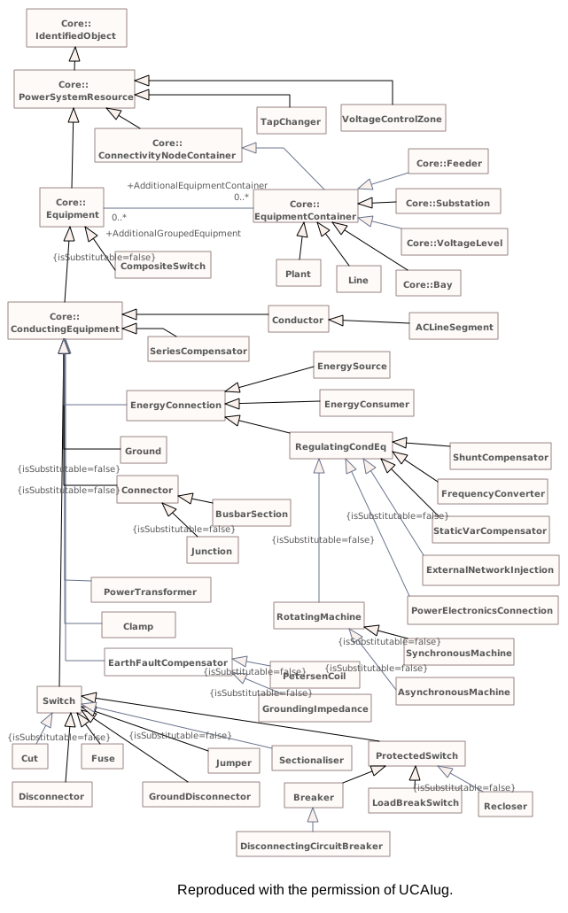
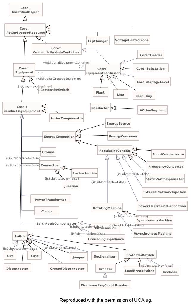
Diagram notes
This diagram describes inheritance between classes in and related to the Wires package.Diagram metadata — changes
| Baseline | Destination | |
|---|---|---|
| no changes | ||
Diagram notes
This diagram describes inheritance between classes in and related to the Wires package.▦Diagram
changed
Baseline
Destination
▶▦NamingHierarchyPart2i
CHANGED{3A72A435-5BA5-4809-A5DC-560573D58582}
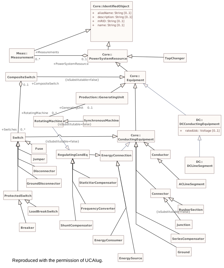
Diagram notes
The diagram shows the lower part of the naming hierarchy. It shows how the Equipment class is further specialized into many subtypes that are all contained by subclasses of the EquipmentContainer. For the subclasses of equipment container refer to part 1 of the diagram.Diagram metadata — changes
| Baseline | Destination | |
|---|---|---|
| no changes | ||
Diagram notes
The diagram shows the lower part of the naming hierarchy. It shows how the Equipment class is further specialized into many subtypes that are all contained by subclasses of the EquipmentContainer. For the subclasses of equipment container refer to part 1 of the diagram.▦Diagram
changed
Baseline
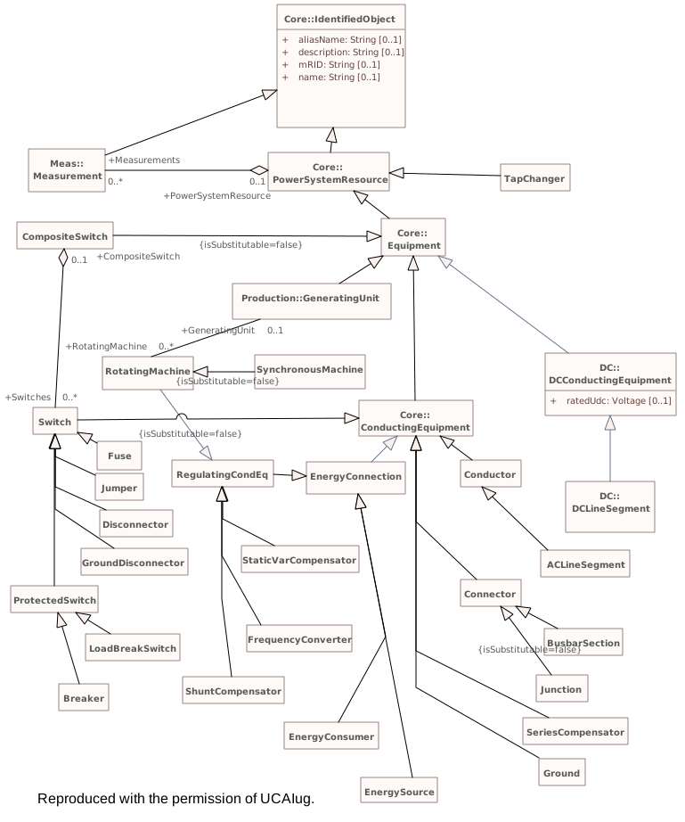
Destination
▶▦RegulatingEquipmenti
CHANGED{F857266A-1599-4d8c-8AC8-29B416B63FA2}
Diagram notes
The diagram shows all classes related to equipment regulation and reactive power compensation.Diagram metadata — changes
| Baseline | Destination | |
|---|---|---|
| ModifiedDate | 2022-06-10 12:00:00 | 2023-02-06 23:10:10 |
Diagram notes
The diagram shows all classes related to equipment regulation and reactive power compensation.▤Metadata
| Baseline | Destination | |
|---|---|---|
| ModifiedDate | 2022-06-10 12:00:00 | 2023-02-06 23:10:10 |
▦Diagram
addedchanged
Baseline
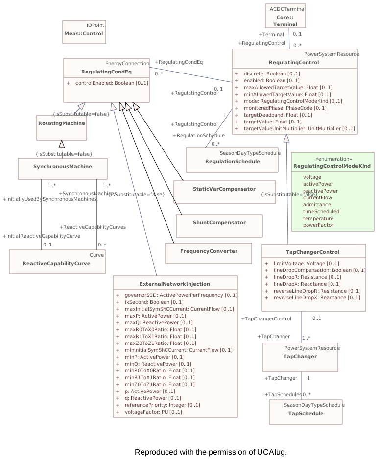
Destination
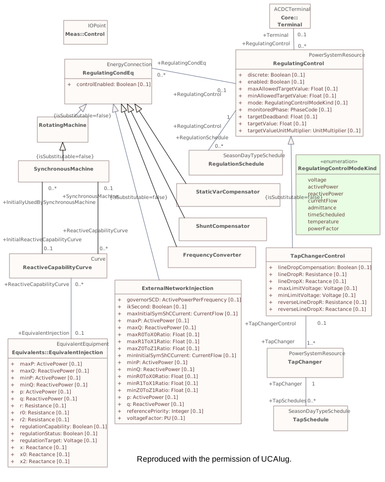
Connectors 1 added · 7 labels movedhover a connector to outline the elements it joins
added(not in this model) – EquivalentInjection
labels moved(not in this model) – (not in this model)
labels moved(not in this model) – (not in this model)
labels moved(not in this model) – RegulatingControl
labels movedRegulatingCondEq – RegulatingControl
labels movedRegulationSchedule – RegulatingControl
labels movedTapChanger – TapChangerControl
labels movedTapSchedule – TapChanger
▶▦Schedulesi
CHANGED{18FA35BC-A253-4a57-A387-6D36B189A250}
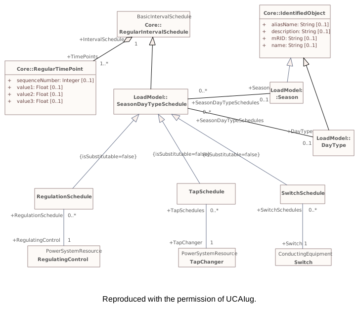
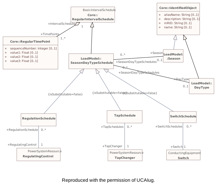
Diagram notes
Shows schedules of wires model.Diagram metadata — changes
| Baseline | Destination | |
|---|---|---|
| no changes | ||
Diagram notes
Shows schedules of wires model.▦Diagram
changed
Baseline
Destination
▶▦ShuntCompensatori
CHANGED{3CAA0009-F451-4e6d-BEDE-2AD7E67D3C35}
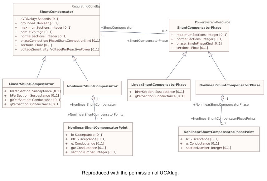
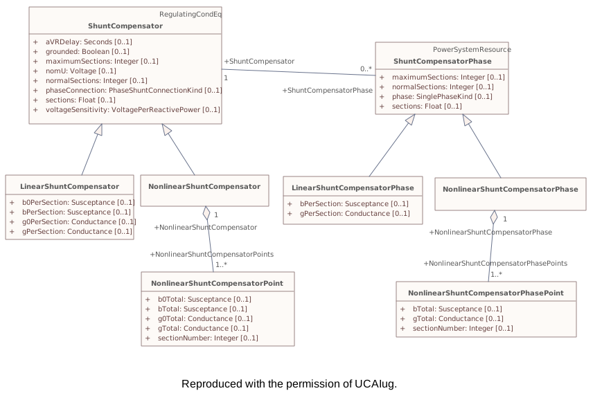
Diagram notes
Shows shunt compensator inheritance structure.Diagram metadata — changes
| Baseline | Destination | |
|---|---|---|
| ModifiedDate | 2022-06-10 12:00:00 | 2023-02-11 11:24:26 |
Diagram notes
Shows shunt compensator inheritance structure.▤Metadata
| Baseline | Destination | |
|---|---|---|
| ModifiedDate | 2022-06-10 12:00:00 | 2023-02-11 11:24:26 |
▦Diagram
changedmoved or resized
Baseline
Destination
Connectors 3 labels movedhover a connector to outline the elements it joins
labels movedNonlinearShuntCompensatorPhasePoint – NonlinearShuntCompensatorPhase
labels movedNonlinearShuntCompensatorPoint – NonlinearShuntCompensator
labels movedShuntCompensator – ShuntCompensatorPhase
▶▦TapChangeri
CHANGED{E6AB0688-D20A-4495-802A-28F4BC2E446D}
Diagram notes
This diagram shows all classes related to the transformer tap model.Diagram metadata — changes
| Baseline | Destination | |
|---|---|---|
| ModifiedDate | 2022-06-10 12:00:00 | 2023-02-11 08:10:03 |
Diagram notes
This diagram shows all classes related to the transformer tap model.▤Metadata
| Baseline | Destination | |
|---|---|---|
| ModifiedDate | 2022-06-10 12:00:00 | 2023-02-11 08:10:03 |
▦Diagram
changedmoved or resized
Baseline
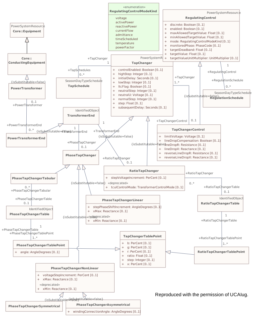
Destination
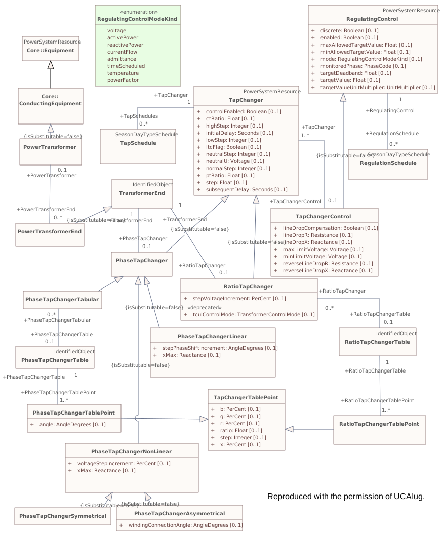
Connectors 5 rerouted · 7 labels movedhover a connector to outline the elements it joins
reroutedRatioTapChangerTablePoint – TapChangerTablePoint
reroutedRegulationSchedule – RegulatingControl
reroutedTapChanger – TapChangerControl
reroutedTapChangerControl – RegulatingControl
reroutedTapSchedule – TapChanger
labels movedPhaseTapChangerTable – PhaseTapChangerTabular
labels movedPhaseTapChangerTablePoint – PhaseTapChangerTable
labels movedPowerTransformer – PowerTransformerEnd
labels movedRatioTapChanger – RatioTapChangerTable
labels movedRatioTapChangerTablePoint – RatioTapChangerTable
labels movedTransformerEnd – PhaseTapChanger
labels movedTransformerEnd – RatioTapChanger
▶▦Transformeri
CHANGED{FA8E6B7F-EAD2-40df-956C-D26D5A54BFC7}
Diagram notes
This diagram shows classes related to the core transformer model, but does not show the tap changer details.Diagram metadata — changes
| Baseline | Destination | |
|---|---|---|
| ModifiedDate | 2022-06-10 12:00:00 | 2023-02-11 09:32:13 |
Diagram notes
This diagram shows classes related to the core transformer model, but does not show the tap changer details.▤Metadata
| Baseline | Destination | |
|---|---|---|
| ModifiedDate | 2022-06-10 12:00:00 | 2023-02-11 09:32:13 |
▦Diagram
moved or resized
Baseline
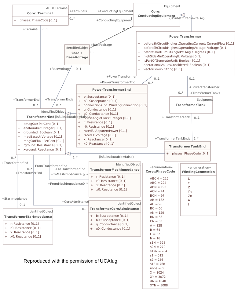
Destination
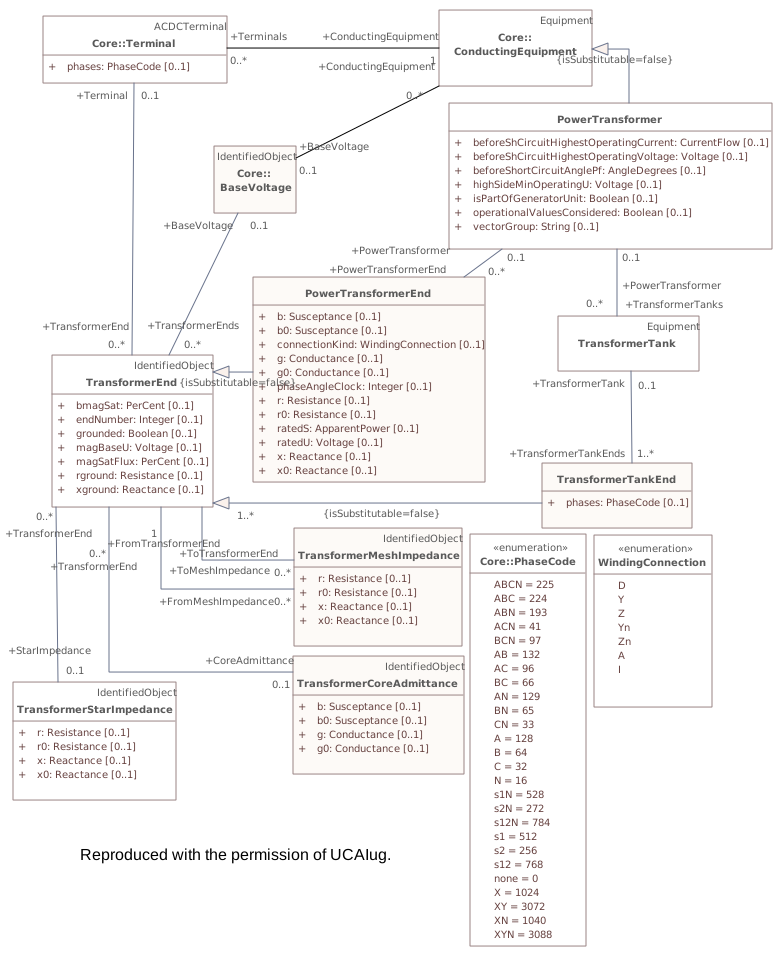
Connectors 3 rerouted · 8 labels movedhover a connector to outline the elements it joins
reroutedTransformerCoreAdmittance – TransformerEnd
reroutedTransformerMeshImpedance – TransformerEnd
reroutedTransformerMeshImpedance – TransformerEnd
labels moved(not in this model) – ConductingEquipment
labels movedPowerTransformer – PowerTransformerEnd
labels movedTerminal – ConductingEquipment
labels movedTransformerEnd – (not in this model)
labels movedTransformerEnd – Terminal
labels movedTransformerEnd – TransformerStarImpedance
labels movedTransformerTank – PowerTransformer
labels movedTransformerTankEnd – TransformerTank
▶LoadModeli
CHANGED{427D9D64-CDA2-4070-AAC6-04A32F290872}
Package notes
This package is responsible for modelling the energy consumers and the system load as curves and associated curve data. Special circumstances that may affect the load, such as seasons and day types, are also included here.
This information is used by Load Forecasting and Load Management.Package metadata — changes
| Baseline | Destination | |
|---|---|---|
| no changes | ||
Tagged values — changes
| Baseline | Destination | |
|---|---|---|
| uri | (no tag) | http://ucaiug.org/CIM/LoadModel/1.0 |
| version | (no tag) | 1.0.0 |
Package notes
This package is responsible for modelling the energy consumers and the system load as curves and associated curve data. Special circumstances that may affect the load, such as seasons and day types, are also included here.
This information is used by Load Forecasting and Load Management.Tagged values
| Baseline | Destination | |
|---|---|---|
| uri | (no tag) | http://ucaiug.org/CIM/LoadModel/1.0 |
| version | (no tag) | 1.0.0 |
Package 'LoadModel' has no changes to the 16 classes it contains.
Package 'LoadModel' has no changes to the 1 diagrams it contains.
▶Generationi
CHANGED{6B50A1FD-22E9-4abc-B0B7-F46BBD8B33AE}
Package notes
This package contains packages that have information for Unit Commitment and Economic Dispatch of hydro and thermal generating units, Load Forecasting, Automatic Generation Control, and unit modeling for Training Simulation.Package metadata — changes
| Baseline | Destination | |
|---|---|---|
| no changes | ||
Tagged values — changes
| Baseline | Destination | |
|---|---|---|
| uri | (no tag) | http://ucaiug.org/CIM/Generation/1.0 |
| version | (no tag) | 1.0.0 |
Package notes
This package contains packages that have information for Unit Commitment and Economic Dispatch of hydro and thermal generating units, Load Forecasting, Automatic Generation Control, and unit modeling for Training Simulation.Tagged values
| Baseline | Destination | |
|---|---|---|
| uri | (no tag) | http://ucaiug.org/CIM/Generation/1.0 |
| version | (no tag) | 1.0.0 |
▶GenerationTrainingSimulationi
CHANGED{D3C36399-A1D6-4491-A975-06B94A5A1258}
Package notes
The GenerationTrainingSimululation package contains prime movers, such as turbines and boilers, which are needed for simulation and educational purposes.Package metadata — changes
| Baseline | Destination | |
|---|---|---|
| no changes | ||
Tagged values — changes
| Baseline | Destination | |
|---|---|---|
| uri | (no tag) | http://ucaiug.org/CIM/GenerationTrainingSimulation/1.0 |
| version | (no tag) | 1.0.0 |
Package notes
The GenerationTrainingSimululation package contains prime movers, such as turbines and boilers, which are needed for simulation and educational purposes.Tagged values
| Baseline | Destination | |
|---|---|---|
| uri | (no tag) | http://ucaiug.org/CIM/GenerationTrainingSimulation/1.0 |
| version | (no tag) | 1.0.0 |
Package 'GenerationTrainingSimulation' has no changes to the 15 classes it contains.
Package 'GenerationTrainingSimulation' has no changes to the 2 diagrams it contains.
▶Productioni
CHANGED{39719C4D-64F6-4704-8202-8CAEF5179709}
Package notes
The production package is responsible for classes which describe various kinds of generators. These classes also provide production costing information which is used to economically allocate demand among committed units and calculate reserve quantities.Package metadata — changes
| Baseline | Destination | |
|---|---|---|
| no changes | ||
Tagged values — changes
| Baseline | Destination | |
|---|---|---|
| uri | (no tag) | http://ucaiug.org/CIM/Production/1.0 |
| version | (no tag) | 1.0.0 |
Package notes
The production package is responsible for classes which describe various kinds of generators. These classes also provide production costing information which is used to economically allocate demand among committed units and calculate reserve quantities.Tagged values
| Baseline | Destination | |
|---|---|---|
| uri | (no tag) | http://ucaiug.org/CIM/Production/1.0 |
| version | (no tag) | 1.0.0 |
Package 'Production' has no changes to the 49 classes it contains.
Package 'Production' has no changes to the 6 diagrams it contains.
Package 'Generation' has no changes to the 1 diagrams it contains.
▶DCi
CHANGED{6CA575E7-020B-40d8-B841-027BF8B51BE9}
Package notes
This package contains model for direct current equipment and controls.Package metadata — changes
| Baseline | Destination | |
|---|---|---|
| no changes | ||
Tagged values — changes
| Baseline | Destination | |
|---|---|---|
| uri | (no tag) | http://ucaiug.org/CIM/DC/1.0 |
| version | (no tag) | 1.0.0 |
Package notes
This package contains model for direct current equipment and controls.Tagged values
| Baseline | Destination | |
|---|---|---|
| uri | (no tag) | http://ucaiug.org/CIM/DC/1.0 |
| version | (no tag) | 1.0.0 |
▶DocDCi61970-301 template for documentation of examples and comments on modelling principles.
CHANGED{EF6D1D39-2542-4779-9A28-92713646EFF1}
Package notes (destination, redlined)
This package contains diagrams that will not be printed from the package context (within DC package), but you can and should use diagram placeholders in the Package metadata — changes
| Baseline | Destination | |
|---|---|---|
| no changes | ||
Tagged values — changes
| Baseline | Destination | |
|---|---|---|
| uri | (no tag) | http://ucaiug.org/CIM/DocDC/1.0 |
| version | (no tag) | 1.0.0 |
Package notes (destination, redlined)
This package contains diagrams that will not be printed from the package context (within DC package), but you can and should use diagram placeholders in the Tagged values
| Baseline | Destination | |
|---|---|---|
| uri | (no tag) | http://ucaiug.org/CIM/DocDC/1.0 |
| version | (no tag) | 1.0.0 |
▶DCDetailedDiagramsrenamed from DetailedDiagramsi
MOVEDfrom
Package notes
This package contains instances used in instance diagrams for DC sample modelling.Package metadata — changes
| Baseline | Destination | |
|---|---|---|
| Name | DetailedDiagrams | DCDetailedDiagrams |
| ParentPackage | DC | DocDC |
Tagged values — changes
| Baseline | Destination | |
|---|---|---|
| uri | (no tag) | http://ucaiug.org/CIM/DCDetailedDiagrams/1.0 |
| version | (no tag) | 1.0.0 |
DC{AA9F7D9F-530C-495f-B9C0-42FCE7699AAA}Package notes
This package contains instances used in instance diagrams for DC sample modelling.Tagged values
| Baseline | Destination | |
|---|---|---|
| uri | (no tag) | http://ucaiug.org/CIM/DCDetailedDiagrams/1.0 |
| version | (no tag) | 1.0.0 |
Changed diagrams (5)
▶▦DCContainmentSymmetricalMonopolei
CHANGED{5984E6FC-9AEB-4880-8755-0864E37B183F}
Diagram notes (destination, redlined)
This an example of DC containment symmetrical monopole.Diagram metadata — changes
| Baseline | Destination | |
|---|---|---|
| ModifiedDate | 2022-06-10 12:10:34 | 2023-02-11 07:30:17 |
Diagram notes (destination, redlined)
This an example of DC containment symmetrical monopole.▤Metadata
| Baseline | Destination | |
|---|---|---|
| ModifiedDate | 2022-06-10 12:10:34 | 2023-02-11 07:30:17 |
Diagram 'DCContainmentSymmetricalMonopole' has no other changes. The shows its notes and every changed property.
▶▦DCSampleAsymmetricalMonopolei
CHANGED{8F6A8C77-3450-47f7-8D86-73F661F36E81}
Diagram notes (destination, redlined)
This an example of DC asymmetrical monopole.Diagram metadata — changes
| Baseline | Destination | |
|---|---|---|
| ModifiedDate | 2022-06-10 12:11:39 | 2023-02-11 07:30:58 |
Diagram notes (destination, redlined)
This an example of DC asymmetrical monopole.▤Metadata
| Baseline | Destination | |
|---|---|---|
| ModifiedDate | 2022-06-10 12:11:39 | 2023-02-11 07:30:58 |
Diagram 'DCSampleAsymmetricalMonopole' has no other changes. The shows its notes and every changed property.
▶▦DCSampleBipolei
CHANGED{4112E113-03D6-48d6-931E-BCB784F3E923}
Diagram notes (destination, redlined)
This an example of DC bipole.Diagram metadata — changes
| Baseline | Destination | |
|---|---|---|
| ModifiedDate | 2022-06-10 12:11:40 | 2023-02-11 07:31:10 |
Diagram notes (destination, redlined)
This an example of DC bipole.▤Metadata
| Baseline | Destination | |
|---|---|---|
| ModifiedDate | 2022-06-10 12:11:40 | 2023-02-11 07:31:10 |
Diagram 'DCSampleBipole' has no other changes. The shows its notes and every changed property.
▶▦DCSampleContainmentBipolei
CHANGED{0038B4B7-FEB6-4aa7-9A82-CB7E91177291}
Diagram notes (destination, redlined)
This an example of containment of bipole.Diagram metadata — changes
| Baseline | Destination | |
|---|---|---|
| ModifiedDate | 2022-06-10 12:10:34 | 2023-02-11 07:30:37 |
Diagram notes (destination, redlined)
This an example of containment of bipole.▤Metadata
| Baseline | Destination | |
|---|---|---|
| ModifiedDate | 2022-06-10 12:10:34 | 2023-02-11 07:30:37 |
Diagram 'DCSampleContainmentBipole' has no other changes. The shows its notes and every changed property.
▶▦DCSampleSymmetricalMonopolei
CHANGED{053C4907-6F2C-40b2-934C-BCBE394FCE85}
Diagram notes (destination, redlined)
This an example of DC symmetrical monopole.Diagram metadata — changes
| Baseline | Destination | |
|---|---|---|
| ModifiedDate | 2022-06-10 12:11:39 | 2023-02-11 07:30:49 |
Diagram notes (destination, redlined)
This an example of DC symmetrical monopole.▤Metadata
| Baseline | Destination | |
|---|---|---|
| ModifiedDate | 2022-06-10 12:11:39 | 2023-02-11 07:30:49 |
Diagram 'DCSampleSymmetricalMonopole' has no other changes. The shows its notes and every changed property.
Changed classes (3)
▶⚙DCSwitchi
CHANGED{70FF7870-9AC4-453d-BF3E-7FD0F9E7193E}
Class notes
A switch within the DC system.Class metadata — changes
| Baseline | Destination | |
|---|---|---|
| no changes | ||
Tagged values — changes
| Baseline | Destination | |
|---|---|---|
| no changes | ||
Class notes
A switch within the DC system.≡Attributes
| Attribute | Baseline | Destination | Notes (destination, redlined) | |||||||||||||||||||||||||||||||||||||||||||||
|---|---|---|---|---|---|---|---|---|---|---|---|---|---|---|---|---|---|---|---|---|---|---|---|---|---|---|---|---|---|---|---|---|---|---|---|---|---|---|---|---|---|---|---|---|---|---|---|---|
| lockedi{9137FEB5-CB36-4089-9942-5053FDD60870}show details | did not exist | Boolean [0..1] | If true, the switch is locked. The resulting switch state is a combination of locked and DCSwitch.open attributes as follows: <ul> <li>locked=true and DCSwitch.open=true. The resulting state is open and locked;</li> <li>locked=false and DCSwitch.open=true. The resulting state is open;</li> <li>locked=false and DCSwitch.open=false. The resulting state is closed.</li> </ul> | |||||||||||||||||||||||||||||||||||||||||||||
Attribute notes If true, the switch is locked. The resulting switch state is a combination of locked and DCSwitch.open attributes as follows:
<ul>
<li>locked=true and DCSwitch.open=true. The resulting state is open and locked;</li>
<li>locked=false and DCSwitch.open=true. The resulting state is open;</li>
<li>locked=false and DCSwitch.open=false. The resulting state is closed.</li>
</ul>Attribute metadata — changes
Tagged values — changes
| ||||||||||||||||||||||||||||||||||||||||||||||||
| normalOpeni{74566069-91E2-4a58-BFBA-B3FBF973F08D}show details | did not exist | Boolean [0..1] | The attribute is used in cases when no Measurement for the status value is present. If the DCSwitch has a status measurement the Discrete.normalValue is expected to match with the DCSwitch.normalOpen. | |||||||||||||||||||||||||||||||||||||||||||||
Attribute notes The attribute is used in cases when no Measurement for the status value is present. If the DCSwitch has a status measurement the Discrete.normalValue is expected to match with the DCSwitch.normalOpen.Attribute metadata — changes
Tagged values — changes
| ||||||||||||||||||||||||||||||||||||||||||||||||
| openi{65B17E75-F176-4e34-840B-5FC65F538BFF}show details | did not exist | Boolean [0..1] | The attribute tells if the switch is considered open when used as input to topology processing. | |||||||||||||||||||||||||||||||||||||||||||||
Attribute notes The attribute tells if the switch is considered open when used as input to topology processing.Attribute metadata — changes
Tagged values — changes
| ||||||||||||||||||||||||||||||||||||||||||||||||
| retainedi{410C425F-A18A-49e2-BF38-79D0C7F8AB48}show details | did not exist | Boolean [0..1] | Branch is retained in the topological solution. The flow through retained switches will normally be calculated in power flow. | |||||||||||||||||||||||||||||||||||||||||||||
Attribute notes Branch is retained in the topological solution. The flow through retained switches will normally be calculated in power flow.Attribute metadata — changes
Tagged values — changes
| ||||||||||||||||||||||||||||||||||||||||||||||||
▶⚙VsCapabilityCurvei
CHANGED{64F5C25B-18FF-4bb5-AA4C-F66F8EE815D5}
Class notes
The P-Q capability curve for a voltage source converter, with P on X-axis and Qmin and Qmax on Y1-axis and Y2-axis.Class metadata — changes
| Baseline | Destination | |
|---|---|---|
| no changes | ||
Tagged values — changes
| Baseline | Destination | |
|---|---|---|
| no changes | ||
Class notes
The P-Q capability curve for a voltage source converter, with P on X-axis and Qmin and Qmax on Y1-axis and Y2-axis.≡Attributes
| Attribute | Baseline | Destination | Notes (destination, redlined) | |||||||||||||||||||||||||||||||||||||||||||||
|---|---|---|---|---|---|---|---|---|---|---|---|---|---|---|---|---|---|---|---|---|---|---|---|---|---|---|---|---|---|---|---|---|---|---|---|---|---|---|---|---|---|---|---|---|---|---|---|---|
| referenceVoltagei{D8941980-3CDC-4e75-A774-125751955220}show details | did not exist | Voltage [0..1] | The reference voltage for which the capability curve is valid. | |||||||||||||||||||||||||||||||||||||||||||||
Attribute notes The reference voltage for which the capability curve is valid.Attribute metadata — changes
Tagged values — changes
| ||||||||||||||||||||||||||||||||||||||||||||||||
⇄Links
CHANGEDAssociation{088AB6E2-983D-4208-B04F-916A1B2C598B}
→
DestinationVsConverter role VsConverterDCSidesVsConverter [0..*0..1] → VsCapabilityCurve role CapabilityCurve [0..10..*]
Source end — VsConverter
| Baseline | Destination | |
|---|---|---|
| Cardinality | 0..* | 0..1 |
| Role | Vs | Vs |
| RoleNote | All converters with this capability curve. |
Target end — CapabilityCurve
| Baseline | Destination | |
|---|---|---|
| Cardinality | 0..1 | 0..* |
▶⚙VsConverteri
CHANGED{D3B18BC2-AB54-475c-A731-6EBA3D738BF7}
Class notes
DC side of the voltage source converter (VSC).Class metadata — changes
| Baseline | Destination | |
|---|---|---|
| no changes | ||
Tagged values — changes
| Baseline | Destination | |
|---|---|---|
| no changes | ||
Class notes
DC side of the voltage source converter (VSC).⇄Links
CHANGEDAssociation{088AB6E2-983D-4208-B04F-916A1B2C598B}
→
DestinationVsConverter role VsConverterDCSidesVsConverter [0..*0..1] → VsCapabilityCurve role CapabilityCurve [0..10..*]
Source end — VsConverter
| Baseline | Destination | |
|---|---|---|
| Cardinality | 0..* | 0..1 |
| Role | Vs | Vs |
| RoleNote | All converters with this capability curve. |
Target end — CapabilityCurve
| Baseline | Destination | |
|---|---|---|
| Cardinality | 0..1 | 0..* |
Changed diagrams (2)
▶▦ACDCConverteri
CHANGED{D8B07844-D3DD-4829-B42B-24F6109C6F13}
Diagram notes
This diagram shows classes used to model DC converters.Diagram metadata — changes
| Baseline | Destination | |
|---|---|---|
| ModifiedDate | 2022-06-10 12:08:00 | 2023-02-07 20:35:19 |
Diagram notes
This diagram shows classes used to model DC converters.▤Metadata
| Baseline | Destination | |
|---|---|---|
| ModifiedDate | 2022-06-10 12:08:00 | 2023-02-07 20:35:19 |
▦Diagram
changed
Baseline
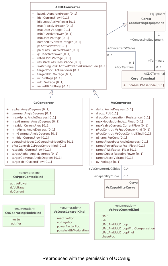
Destination
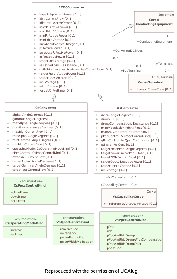
Connectors 1 rerouted · 2 labels movedhover a connector to outline the elements it joins
reroutedVsConverter – VsCapabilityCurve
labels movedACDCConverter – Terminal
labels movedTerminal – ConductingEquipment
▶▦DCEquipmenti
CHANGED{A060A742-BA22-4a1c-A24F-5862D1F35B87}
Diagram notes
The diagram show the DC equipment model.Diagram metadata — changes
| Baseline | Destination | |
|---|---|---|
| ModifiedDate | 2022-06-10 12:08:44 | 2023-02-06 21:40:51 |
Diagram notes
The diagram show the DC equipment model.▤Metadata
| Baseline | Destination | |
|---|---|---|
| ModifiedDate | 2022-06-10 12:08:44 | 2023-02-06 21:40:51 |
▦Diagram
changedmoved or resized
Baseline
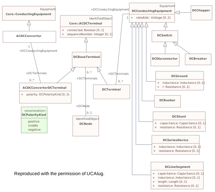
Destination
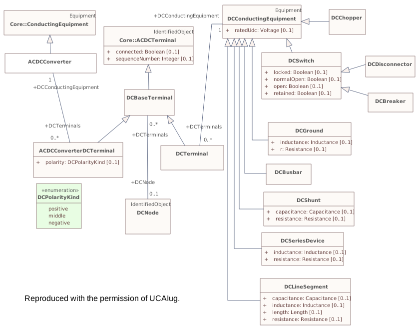
Connectors 2 rerouted · 3 labels movedhover a connector to outline the elements it joins
reroutedDCBreaker – DCSwitch
reroutedDCDisconnector – DCSwitch
labels movedACDCConverterDCTerminal – ACDCConverter
labels movedDCConductingEquipment – DCTerminal
labels movedDCNode – DCBaseTerminal
▶Equivalentsi
CHANGED{32F75AB7-7839-4933-BE8C-F162A464FE41}
Package notes
The equivalents package models equivalent networks.Package metadata — changes
| Baseline | Destination | |
|---|---|---|
| no changes | ||
Tagged values — changes
| Baseline | Destination | |
|---|---|---|
| uri | (no tag) | http://ucaiug.org/CIM/Equivalents/1.0 |
| version | (no tag) | 1.0.0 |
Package notes
The equivalents package models equivalent networks.Tagged values
| Baseline | Destination | |
|---|---|---|
| uri | (no tag) | http://ucaiug.org/CIM/Equivalents/1.0 |
| version | (no tag) | 1.0.0 |
Changed classes (1)
▶⚙EquivalentInjectioniThis class represents equivalent injections (generation or load). Voltage regulation is allowed only at the point of connection. This class represents equivalent injections (generation or load). Voltage regulation is allowed only at the point of connection. Using EquivalentInjection to model a distribution network equivalent is recommended practice instead of using ExternalNetworkInjection-s if it is not necessary that the equivalent contains detailed information representing a short circuit equivalent according to IEC 60909 which is relevant for short circuit studies.
CHANGED{9749AD93-8F33-48c8-9291-02B9D671C172}
Class notes (destination, redlined)
Class metadata — changes
| Baseline | Destination | |
|---|---|---|
| no changes | ||
Tagged values — changes
| Baseline | Destination | |
|---|---|---|
| no changes | ||
Class notes (destination, redlined)
⇄Links
CHANGEDAssociation{FC08DB44-00BE-4bc5-8DE9-3538FD5307B8}
BaselineReactiveCapabilityCurve role ReactiveCapabilityCurve [0..1] → EquivalentInjection role EquivalentInjection [0..*]
→
DestinationReactiveCapabilityCurve role ReactiveCapabilityCurve [0..10..*] → EquivalentInjection role EquivalentInjection [0..*0..1]
Source end — ReactiveCapabilityCurve
| Baseline | Destination | |
|---|---|---|
| Cardinality | 0..1 | 0..* |
Target end — EquivalentInjection
| Baseline | Destination | |
|---|---|---|
| Cardinality | 0..* | 0..1 |
Changed diagrams (1)
▶▦Maini
CHANGED{15613B15-ECE0-47f2-B5D5-CBA4AA111746}
Diagram notes
Shows model for equivalent networks.Diagram metadata — changes
| Baseline | Destination | |
|---|---|---|
| no changes | ||
Diagram notes
Shows model for equivalent networks.▦Diagram
changed
Baseline
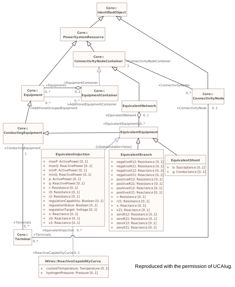
Destination
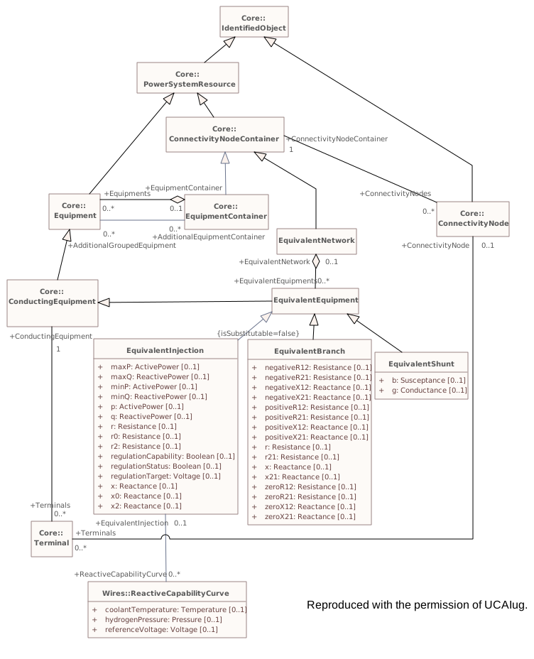
Connectors 1 labels changedhover a connector to outline the elements it joins
labels changedReactiveCapabilityCurve – EquivalentInjectionmultiplicity
▶AuxiliaryEquipmenti
CHANGED{FF7DBBED-8801-4db6-A94B-3AE5E6FFFE95}
Package notes
Contains equipment which is not normal conducting equipment such as sensors, fault locators, and surge protectors. These devices do not define power carrying topological connections as conducting equipment, but are associated to terminals of other conducting equipment.Package metadata — changes
| Baseline | Destination | |
|---|---|---|
| no changes | ||
Tagged values — changes
| Baseline | Destination | |
|---|---|---|
| uri | (no tag) | http://ucaiug.org/CIM/AuxiliaryEquipment/1.0 |
| version | (no tag) | 1.0.0 |
Package notes
Contains equipment which is not normal conducting equipment such as sensors, fault locators, and surge protectors. These devices do not define power carrying topological connections as conducting equipment, but are associated to terminals of other conducting equipment.Tagged values
| Baseline | Destination | |
|---|---|---|
| uri | (no tag) | http://ucaiug.org/CIM/AuxiliaryEquipment/1.0 |
| version | (no tag) | 1.0.0 |
Package 'AuxiliaryEquipment' has no changes to the 9 classes it contains.
Package 'AuxiliaryEquipment' has no changes to the 1 diagrams it contains.
▶Measi
CHANGED{6B58A5C3-5CC1-4320-A9D3-2CABB8F9399E}
Package notes
Contains entities that describe dynamic measurement data exchanged between applications.Package metadata — changes
| Baseline | Destination | |
|---|---|---|
| no changes | ||
Tagged values — changes
| Baseline | Destination | |
|---|---|---|
| uri | (no tag) | http://ucaiug.org/CIM/Meas/1.0 |
| version | (no tag) | 1.0.0 |
Package notes
Contains entities that describe dynamic measurement data exchanged between applications.Tagged values
| Baseline | Destination | |
|---|---|---|
| uri | (no tag) | http://ucaiug.org/CIM/Meas/1.0 |
| version | (no tag) | 1.0.0 |
Changed classes (2)
▶⚙Controli
CHANGED{4EEEE27D-42CD-4efc-8F74-3655BF703F4E}
Class notes
Control is used for supervisory/device control. It represents control outputs that are used to change the state in a process, e.g. close or open breaker, a set point value or a raise lower command.Class metadata — changes
| Baseline | Destination | |
|---|---|---|
| no changes | ||
Tagged values — changes
| Baseline | Destination | |
|---|---|---|
| no changes | ||
Class notes
Control is used for supervisory/device control. It represents control outputs that are used to change the state in a process, e.g. close or open breaker, a set point value or a raise lower command.⇄Links
CHANGEDAssociation{55F3693A-6960-486a-AEB0-EEBB67B10D9A}
→
Source end — ControlAction
| Baseline | Destination | |
|---|---|---|
| RoleNote | The control action that is performed on the control | The control action that is performed on the control. |
Target end
no changes
▶⚙Measurementi
CHANGED{AB1758FA-3A4D-478f-BE4F-ADC8E2F886CC}
Class notes
A Measurement represents any measured, calculated or non-measured non-calculated quantity. Any piece of equipment may contain Measurements, e.g. a substation may have temperature measurements and door open indications, a transformer may have oil temperature and tank pressure measurements, a bay may contain a number of power flow measurements and a Breaker may contain a switch status measurement.
The PSR - Measurement association is intended to capture this use of Measurement and is included in the naming hierarchy based on EquipmentContainer. The naming hierarchy typically has Measurements as leaves, e.g. Substation-VoltageLevel-Bay-Switch-Measurement.
Some Measurements represent quantities related to a particular sensor location in the network, e.g. a voltage transformer (VT) or potential transformer (PT) at a busbar or a current transformer (CT) at the bar between a breaker and an isolator. The sensing position is not captured in the PSR - Measurement association. Instead it is captured by the Measurement - Terminal association that is used to define the sensing location in the network topology. The location is defined by the connection of the Terminal to ConductingEquipment.
If both a Terminal and PSR are associated, and the PSR is of type ConductingEquipment, the associated Terminal should belong to that ConductingEquipment instance.
When the sensor location is needed both Measurement-PSR and Measurement-Terminal are used. The Measurement-Terminal association is never used alone.Class metadata — changes
| Baseline | Destination | |
|---|---|---|
| no changes | ||
Tagged values — changes
| Baseline | Destination | |
|---|---|---|
| no changes | ||
Class notes
A Measurement represents any measured, calculated or non-measured non-calculated quantity. Any piece of equipment may contain Measurements, e.g. a substation may have temperature measurements and door open indications, a transformer may have oil temperature and tank pressure measurements, a bay may contain a number of power flow measurements and a Breaker may contain a switch status measurement.
The PSR - Measurement association is intended to capture this use of Measurement and is included in the naming hierarchy based on EquipmentContainer. The naming hierarchy typically has Measurements as leaves, e.g. Substation-VoltageLevel-Bay-Switch-Measurement.
Some Measurements represent quantities related to a particular sensor location in the network, e.g. a voltage transformer (VT) or potential transformer (PT) at a busbar or a current transformer (CT) at the bar between a breaker and an isolator. The sensing position is not captured in the PSR - Measurement association. Instead it is captured by the Measurement - Terminal association that is used to define the sensing location in the network topology. The location is defined by the connection of the Terminal to ConductingEquipment.
If both a Terminal and PSR are associated, and the PSR is of type ConductingEquipment, the associated Terminal should belong to that ConductingEquipment instance.
When the sensor location is needed both Measurement-PSR and Measurement-Terminal are used. The Measurement-Terminal association is never used alone.⇄Links
CHANGEDAssociation{016DD996-A1EA-4bb6-8349-AF38EEDFF7AD}
→
Source end — Asset
| Baseline | Destination | |
|---|---|---|
| RoleNote | Asset that has a measurement | Asset that has a measurement. |
Target end
no changes
CHANGEDAssociation{0566ECD1-879E-43fc-AFB0-A8B79BFC4DEE}
→
Source end — MeasurementAction
| Baseline | Destination | |
|---|---|---|
| RoleNote | The measurement action that is performed on the measurement | The measurement action that is performed on the measurement. |
Target end — Measurement
| Baseline | Destination | |
|---|---|---|
| RoleNote | The measurement that the measurement action is performed on | The measurement that the measurement action is performed on. |
Package 'Meas' has no changes to the 5 diagrams it contains.
▶Topologyi
CHANGED{E44AA599-D1DD-4d0c-8487-AE8BE9E6FEEB}
Package notes
An extension to the Core Package that, in association with the Terminal class, models Connectivity, that is the physical definition of how equipment is connected together. In addition it models Topology, that is the logical definition of how equipment is connected via closed switches. The Topology definition is independent of the other electrical characteristics.Package metadata — changes
| Baseline | Destination | |
|---|---|---|
| no changes | ||
Tagged values — changes
| Baseline | Destination | |
|---|---|---|
| uri | (no tag) | http://ucaiug.org/CIM/Topology/1.0 |
| version | (no tag) | 1.0.0 |
Package notes
An extension to the Core Package that, in association with the Terminal class, models Connectivity, that is the physical definition of how equipment is connected together. In addition it models Topology, that is the logical definition of how equipment is connected via closed switches. The Topology definition is independent of the other electrical characteristics.Tagged values
| Baseline | Destination | |
|---|---|---|
| uri | (no tag) | http://ucaiug.org/CIM/Topology/1.0 |
| version | (no tag) | 1.0.0 |
Package 'Topology' has no changes to the 3 classes it contains.
Package 'Topology' has no changes to the 2 diagrams it contains.
▶DiagramLayouti
CHANGED{BD6471E7-9929-4251-A731-BB65A6ABD2BF}
Package notes
This package describes diagram layout. This describes how objects are arranged in a coordinate system rather than how they are rendered.Package metadata — changes
| Baseline | Destination | |
|---|---|---|
| no changes | ||
Tagged values — changes
| Baseline | Destination | |
|---|---|---|
| uri | (no tag) | http://ucaiug.org/CIM/DiagramLayout/1.0 |
| version | (no tag) | 1.0.0 |
Package notes
This package describes diagram layout. This describes how objects are arranged in a coordinate system rather than how they are rendered.Tagged values
| Baseline | Destination | |
|---|---|---|
| uri | (no tag) | http://ucaiug.org/CIM/DiagramLayout/1.0 |
| version | (no tag) | 1.0.0 |
Package 'DiagramLayout' has no changes to the 9 classes it contains.
Package 'DiagramLayout' has no changes to the 1 diagrams it contains.
▶OperationalLimitsi
CHANGED{CCAAF4EA-4C50-4438-86F9-63852950B3CA}
Package notes
This package models a specification of limits associated with equipment and other operational entities.Package metadata — changes
| Baseline | Destination | |
|---|---|---|
| no changes | ||
Tagged values — changes
| Baseline | Destination | |
|---|---|---|
| uri | (no tag) | http://ucaiug.org/CIM/OperationalLimits/1.0 |
| version | (no tag) | 1.0.0 |
Package notes
This package models a specification of limits associated with equipment and other operational entities.Tagged values
| Baseline | Destination | |
|---|---|---|
| uri | (no tag) | http://ucaiug.org/CIM/OperationalLimits/1.0 |
| version | (no tag) | 1.0.0 |
Package 'OperationalLimits' has no changes to the 10 classes it contains.
Package 'OperationalLimits' has no changes to the 2 diagrams it contains.
▶ControlAreai
CHANGED{3A4198A2-F8DC-4ff1-B669-3064688AF4DD}
Package notes
The ControlArea package models area specifications which can be used for a variety of purposes. The package as a whole models potentially overlapping control area specifications for the purpose of actual generation control, load forecast area load capture, or powerflow based analysis.Package metadata — changes
| Baseline | Destination | |
|---|---|---|
| no changes | ||
Tagged values — changes
| Baseline | Destination | |
|---|---|---|
| uri | (no tag) | http://ucaiug.org/CIM/ControlArea/1.0 |
| version | (no tag) | 1.0.0 |
Package notes
The ControlArea package models area specifications which can be used for a variety of purposes. The package as a whole models potentially overlapping control area specifications for the purpose of actual generation control, load forecast area load capture, or powerflow based analysis.Tagged values
| Baseline | Destination | |
|---|---|---|
| uri | (no tag) | http://ucaiug.org/CIM/ControlArea/1.0 |
| version | (no tag) | 1.0.0 |
Package 'ControlArea' has no changes to the 6 classes it contains.
Package 'ControlArea' has no changes to the 3 diagrams it contains.
▶Contingencyi
CHANGED{5AFF4730-5CFE-48e6-961A-077143DE2082}
Package notes
Contingencies to be studied.Package metadata — changes
| Baseline | Destination | |
|---|---|---|
| no changes | ||
Tagged values — changes
| Baseline | Destination | |
|---|---|---|
| uri | (no tag) | http://ucaiug.org/CIM/Contingency/1.0 |
| version | (no tag) | 1.0.0 |
Package notes
Contingencies to be studied.Tagged values
| Baseline | Destination | |
|---|---|---|
| uri | (no tag) | http://ucaiug.org/CIM/Contingency/1.0 |
| version | (no tag) | 1.0.0 |
Package 'Contingency' has no changes to the 4 classes it contains.
Package 'Contingency' has no changes to the 1 diagrams it contains.
▶StateVariablesi
CHANGED{968842F7-ED9B-4b20-A08E-C8ECAAC5DB25}
Package notes
State variables for analysis solutions such as powerflow.Package metadata — changes
| Baseline | Destination | |
|---|---|---|
| no changes | ||
Tagged values — changes
| Baseline | Destination | |
|---|---|---|
| uri | (no tag) | http://ucaiug.org/CIM/StateVariables/1.0 |
| version | (no tag) | 1.0.0 |
Package notes
State variables for analysis solutions such as powerflow.Tagged values
| Baseline | Destination | |
|---|---|---|
| uri | (no tag) | http://ucaiug.org/CIM/StateVariables/1.0 |
| version | (no tag) | 1.0.0 |
Package 'StateVariables' has no changes to the 8 classes it contains.
Changed diagrams (1)
▶▦StateVariablesi
CHANGED{98328D29-4518-4d82-93D9-EC1421E6E8BF}
Diagram notes
The state solution variables as derived from base StateVariable class. Note that specialized state variables are associated with objects derived from IdentifiedObject, but StateVariable does not derive from IdentifiedObject.Diagram metadata — changes
| Baseline | Destination | |
|---|---|---|
| no changes | ||
Diagram notes
The state solution variables as derived from base StateVariable class. Note that specialized state variables are associated with objects derived from IdentifiedObject, but StateVariable does not derive from IdentifiedObject.▦Diagram
changed
Baseline
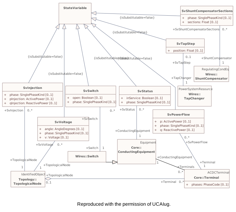
Destination
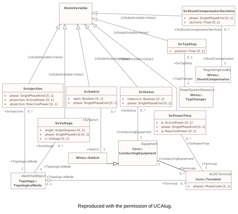
▶Protectioni
CHANGED{3F02E213-ECF8-4f14-9AD5-D4A252FE300A}
Package notes
An extension to the Core and Wires packages that models information for protection equipment such as relays. These entities are used within training simulators and distribution network fault location applications.Package metadata — changes
| Baseline | Destination | |
|---|---|---|
| no changes | ||
Tagged values — changes
| Baseline | Destination | |
|---|---|---|
| uri | (no tag) | http://ucaiug.org/CIM/Protection/1.0 |
| version | (no tag) | 1.0.0 |
Package notes
An extension to the Core and Wires packages that models information for protection equipment such as relays. These entities are used within training simulators and distribution network fault location applications.Tagged values
| Baseline | Destination | |
|---|---|---|
| uri | (no tag) | http://ucaiug.org/CIM/Protection/1.0 |
| version | (no tag) | 1.0.0 |
Package 'Protection' has no changes to the 4 classes it contains.
Package 'Protection' has no changes to the 1 diagrams it contains.
▶Faultsi
CHANGED{59BC9A2E-B8E4-4c5f-B1D8-2C6502296346}
Package notes
The package describes faults that may happen to conducting equipment, e.g. tree falling on a power line.Package metadata — changes
| Baseline | Destination | |
|---|---|---|
| no changes | ||
Tagged values — changes
| Baseline | Destination | |
|---|---|---|
| uri | (no tag) | http://ucaiug.org/CIM/Faults/1.0 |
| version | (no tag) | 1.0.0 |
Package notes
The package describes faults that may happen to conducting equipment, e.g. tree falling on a power line.Tagged values
| Baseline | Destination | |
|---|---|---|
| uri | (no tag) | http://ucaiug.org/CIM/Faults/1.0 |
| version | (no tag) | 1.0.0 |
Package 'Faults' has no changes to the 6 classes it contains.
Package 'Faults' has no changes to the 1 diagrams it contains.
▶SCADAi
CHANGED{C397A471-682D-4757-89C3-C65DCE1842A7}
Package notes
Contains entities to model information used by Supervisory Control and Data Acquisition (SCADA) applications. Supervisory control supports operator control of equipment, such as opening or closing a breaker. Data acquisition gathers telemetered data from various sources. The subtypes of the Telemetry entity deliberately match the UCA and IEC 61850 definitions.
This package also supports alarm presentation but it is not expected to be used by other applications.Package metadata — changes
| Baseline | Destination | |
|---|---|---|
| no changes | ||
Tagged values — changes
| Baseline | Destination | |
|---|---|---|
| uri | (no tag) | http://ucaiug.org/CIM/SCADA/1.0 |
| version | (no tag) | 1.0.0 |
Package notes
Contains entities to model information used by Supervisory Control and Data Acquisition (SCADA) applications. Supervisory control supports operator control of equipment, such as opening or closing a breaker. Data acquisition gathers telemetered data from various sources. The subtypes of the Telemetry entity deliberately match the UCA and IEC 61850 definitions.
This package also supports alarm presentation but it is not expected to be used by other applications.Tagged values
| Baseline | Destination | |
|---|---|---|
| uri | (no tag) | http://ucaiug.org/CIM/SCADA/1.0 |
| version | (no tag) | 1.0.0 |
Package 'SCADA' has no changes to the 7 classes it contains.
Package 'SCADA' has no changes to the 2 diagrams it contains.
▶ICCPConfigurationi
CHANGED{423B82DE-E83D-40a8-A4C8-8EA08513C297}
Package notes
This package models configuration of ICCP required for bilateral exchanges.Package metadata — changes
| Baseline | Destination | |
|---|---|---|
| no changes | ||
Tagged values — changes
| Baseline | Destination | |
|---|---|---|
| uri | (no tag) | http://ucaiug.org/CIM/ICCPConfiguration/1.0 |
| version | (no tag) | 1.0.0 |
Package notes
This package models configuration of ICCP required for bilateral exchanges.Tagged values
| Baseline | Destination | |
|---|---|---|
| uri | (no tag) | http://ucaiug.org/CIM/ICCPConfiguration/1.0 |
| version | (no tag) | 1.0.0 |
▶DocICCPConfigurationrenamed from DetailedDiagramsi
CHANGED{E563C801-A3FC-411f-A0D4-61F43A7C157B}
Package notes (destination, redlined)
This package contains example documentation diagrams.Package metadata — changes
| Baseline | Destination | |
|---|---|---|
| Name | DetailedDiagrams | DocICCPConfiguration |
Tagged values — changes
| Baseline | Destination | |
|---|---|---|
| uri | (no tag) | http://ucaiug.org/CIM/DocICCPConfiguration/1.0 |
| version | (no tag) | 1.0.0 |
Package notes (destination, redlined)
This package contains example documentation diagrams.Tagged values
| Baseline | Destination | |
|---|---|---|
| uri | (no tag) | http://ucaiug.org/CIM/DocICCPConfiguration/1.0 |
| version | (no tag) | 1.0.0 |
Changed diagrams (1)
▶▦ICCPExamplei
CHANGED{4B060A5B-9830-40ac-B58C-9B4AA8F0D330}
Diagram notes
No notes defined in the model.Diagram metadata — changes
| Baseline | Destination | |
|---|---|---|
| ParentPackage | DetailedDiagrams | DocICCPConfiguration |
Diagram notes
No notes defined in the model.▤Metadata
| Baseline | Destination | |
|---|---|---|
| ParentPackage | DetailedDiagrams | DocICCPConfiguration |
Diagram 'ICCPExample' has no other changes. The shows its notes and every changed property.
Package 'ICCPConfiguration' has no changes to the 19 classes it contains.
Package 'ICCPConfiguration' has no changes to the 2 diagrams it contains.
▶DocBaseiin IEC61970-301 with the rest of the normative packages. The diagrams within this package are individually included in this document.
CHANGED{9595963E-B478-4f81-8DE5-EBF73E630358}
Package notes (destination, redlined)
This package contains example documentation diagrams not intended to be documented Package metadata — changes
| Baseline | Destination | |
|---|---|---|
| no changes | ||
Tagged values — changes
| Baseline | Destination | |
|---|---|---|
| uri | (no tag) | http://ucaiug.org/CIM/DocBase/1.0 |
| version | (no tag) | 1.0.0 |
Package notes (destination, redlined)
This package contains example documentation diagrams not intended to be documented Tagged values
| Baseline | Destination | |
|---|---|---|
| uri | (no tag) | http://ucaiug.org/CIM/DocBase/1.0 |
| version | (no tag) | 1.0.0 |
Package 'DocBase' has no changes to the 3 diagrams it contains.
▶Dynamicsithisthe entire clause "Common Information Model Dynamics package" is reproduced from the UML with the permission of UCAIug.
CHANGED{A71B9185-6D48-40f4-B618-485C08C4F269}
Package notes (destination, redlined)
The CIM dynamic model definitions reflect the most common IEEE or, in the case of wind models, IEC, representations of models as well as models included in some of the transient stability software widely used by utilities.
These dynamic models are intended to ensure interoperability between different vendors’ software products currently in use by electric utility energy companies, utilities, Transmission System Operators (TSOs), Regional Transmission Organizations (RTOs), and Independent System Operators (ISOs). It is important to note that each vendor is free to select its own internal implementation of these models. Differences in vendor results, as long as they are within accepted engineering practice, caused by different internal representations, are acceptable.
Unless explicitly stated otherwise, the following modelling conventions are followed:
- limited integrators are of the non-windup type;
- it shall be possible to enter a time constant of zero (where it makes sense).
The information in Package metadata — changes
| Baseline | Destination | |
|---|---|---|
| no changes | ||
Tagged values — changes
| Baseline | Destination | |
|---|---|---|
| uri | http://iec.ch/TC57/CIM/Dynamics/1.0 | http://ucaiug.org/CIM/Dynamics/1.0 |
Package notes (destination, redlined)
The CIM dynamic model definitions reflect the most common IEEE or, in the case of wind models, IEC, representations of models as well as models included in some of the transient stability software widely used by utilities.
These dynamic models are intended to ensure interoperability between different vendors’ software products currently in use by electric utility energy companies, utilities, Transmission System Operators (TSOs), Regional Transmission Organizations (RTOs), and Independent System Operators (ISOs). It is important to note that each vendor is free to select its own internal implementation of these models. Differences in vendor results, as long as they are within accepted engineering practice, caused by different internal representations, are acceptable.
Unless explicitly stated otherwise, the following modelling conventions are followed:
- limited integrators are of the non-windup type;
- it shall be possible to enter a time constant of zero (where it makes sense).
The information in Tagged values
| Baseline | Destination | |
|---|---|---|
| uri | http://iec.ch/TC57/CIM/Dynamics/1.0 | http://ucaiug.org/CIM/Dynamics/1.0 |
▶StandardInterconnectionsi
CHANGED{9E32B79D-9C05-4fe4-9518-A32B1C67637A}
Package notes
This subclause describes the standard interconnections for various types of equipment. These interconnections are understood by the application programs and can be identified based on the presence of one of the key classes with a relationship to the static power flow model: SynchronousMachineDynamics, AsynchronousMachineDynamics, EnergyConsumerDynamics or WindTurbineType3or4Dynamics.
The relationships between classes expressed in the interconnection diagrams are intended to support dynamic behaviour described by either standard models or user-defined models.
In the interconnection diagrams, boxes which are black in colour represent function blocks whose functionality can be provided by one of many standard models or by a user-defined model. Blue boxes represent specific standard models. A dashed box means that the function block or specific standard model is optional.Package metadata — changes
| Baseline | Destination | |
|---|---|---|
| no changes | ||
Tagged values — changes
| Baseline | Destination | |
|---|---|---|
| uri | http://iec.ch/TC57/CIM/StandardInterconnections/1.0 | http://ucaiug.org/CIM/StandardInterconnections/1.0 |
Package notes
This subclause describes the standard interconnections for various types of equipment. These interconnections are understood by the application programs and can be identified based on the presence of one of the key classes with a relationship to the static power flow model: SynchronousMachineDynamics, AsynchronousMachineDynamics, EnergyConsumerDynamics or WindTurbineType3or4Dynamics.
The relationships between classes expressed in the interconnection diagrams are intended to support dynamic behaviour described by either standard models or user-defined models.
In the interconnection diagrams, boxes which are black in colour represent function blocks whose functionality can be provided by one of many standard models or by a user-defined model. Blue boxes represent specific standard models. A dashed box means that the function block or specific standard model is optional.Tagged values
| Baseline | Destination | |
|---|---|---|
| uri | http://iec.ch/TC57/CIM/StandardInterconnections/1.0 | http://ucaiug.org/CIM/StandardInterconnections/1.0 |
▶WindModelsi
CHANGED{6319640C-8A7E-4aae-A1DA-A6DB83723377}
Package notes
Standard interconnections included in this package are according to IEC 61400-27-1:2015.Package metadata — changes
| Baseline | Destination | |
|---|---|---|
| no changes | ||
Tagged values — changes
| Baseline | Destination | |
|---|---|---|
| uri | http://iec.ch/TC57/CIM/WindModels/1.0 | http://ucaiug.org/CIM/WindModels/1.0 |
Package notes
Standard interconnections included in this package are according to IEC 61400-27-1:2015.Tagged values
| Baseline | Destination | |
|---|---|---|
| uri | http://iec.ch/TC57/CIM/WindModels/1.0 | http://ucaiug.org/CIM/WindModels/1.0 |
Package 'WindModels' has no changes to the 6 diagrams it contains.
Package 'StandardInterconnections' has no changes to the 2 classes it contains.
Package 'StandardInterconnections' has no changes to the 10 diagrams it contains.
▶StandardModelsi
CHANGED{1BEB429C-BFD0-49c6-9556-AC7BA58C2202}
Package notes
This subclause contains standard dynamic model specifications grouped into packages by standard function block (type of equipment being modelled).
In the CIM, standard dynamic models are expressed by means of a class named with the standard model name and attributes reflecting each of the parameters necessary to describe the behaviour of an instance of the standard model.Package metadata — changes
| Baseline | Destination | |
|---|---|---|
| no changes | ||
Tagged values — changes
| Baseline | Destination | |
|---|---|---|
| uri | http://iec.ch/TC57/CIM/StandardModels/1.0 | http://ucaiug.org/CIM/StandardModels/1.0 |
Package notes
This subclause contains standard dynamic model specifications grouped into packages by standard function block (type of equipment being modelled).
In the CIM, standard dynamic models are expressed by means of a class named with the standard model name and attributes reflecting each of the parameters necessary to describe the behaviour of an instance of the standard model.Tagged values
| Baseline | Destination | |
|---|---|---|
| uri | http://iec.ch/TC57/CIM/StandardModels/1.0 | http://ucaiug.org/CIM/StandardModels/1.0 |
▶SynchronousMachineDynamicsi
CHANGED{448F8675-D39C-4fe0-9450-2791AE603EFC}
Package notes
For conventional power generating units (e.g., thermal, hydro, combustion turbine), a synchronous machine model represents the electrical characteristics of the generator and the mechanical characteristics of the turbine-generator rotational inertia. Large industrial motors or groups of similar motors can be represented by individual motor models which are represented as generators with negative active power in the static (power flow) data.
The interconnection with the electrical network equations can differ among simulation tools. The tool only needs to know the synchronous machine to establish the correct interconnection. The interconnection with the motor’s equipment could also differ due to input and output signals required by standard models.Package metadata — changes
| Baseline | Destination | |
|---|---|---|
| no changes | ||
Tagged values — changes
| Baseline | Destination | |
|---|---|---|
| uri | http://iec.ch/TC57/CIM/SynchronousMachineDynamics/1.0 | http://ucaiug.org/CIM/SynchronousMachineDynamics/1.0 |
Package notes
For conventional power generating units (e.g., thermal, hydro, combustion turbine), a synchronous machine model represents the electrical characteristics of the generator and the mechanical characteristics of the turbine-generator rotational inertia. Large industrial motors or groups of similar motors can be represented by individual motor models which are represented as generators with negative active power in the static (power flow) data.
The interconnection with the electrical network equations can differ among simulation tools. The tool only needs to know the synchronous machine to establish the correct interconnection. The interconnection with the motor’s equipment could also differ due to input and output signals required by standard models.Tagged values
| Baseline | Destination | |
|---|---|---|
| uri | http://iec.ch/TC57/CIM/SynchronousMachineDynamics/1.0 | http://ucaiug.org/CIM/SynchronousMachineDynamics/1.0 |
Changed classes (1)
▶⚙SynchronousMachineDynamicsi
CHANGED{575BECE2-4C08-40c3-9B81-1C8E6F4FCF8C}
Class notes
Synchronous machine whose behaviour is described by reference to a standard model expressed in one of the following forms:
- simplified (or classical), where a group of generators or motors is not modelled in detail;
- detailed, in equivalent circuit form;
- detailed, in time constant reactance form; or
<font color="#0f0f0f">- by definition of a user-defined model.</font>
<font color="#0f0f0f">It is a common practice to represent small generators by a negative load rather than by a dynamic generator model when performing dynamics simulations. In this case, a SynchronousMachine in the static model is not represented by anything in the dynamics model, instead it is treated as an ordinary load.</font>
<font color="#0f0f0f">Parameter details:</font>
<ol>
<li><font color="#0f0f0f">Synchronous machine parameters such as <i>Xl, Xd, Xp</i> etc. are actually used as inductances in the models,</font> but are commonly referred to as reactances since, at nominal frequency, the PU values are the same. However, some references use the symbol <i>L</i> instead of <i>X</i>.</li>
</ol>Class metadata — changes
| Baseline | Destination | |
|---|---|---|
| no changes | ||
Tagged values — changes
| Baseline | Destination | |
|---|---|---|
| no changes | ||
Class notes
Synchronous machine whose behaviour is described by reference to a standard model expressed in one of the following forms:
- simplified (or classical), where a group of generators or motors is not modelled in detail;
- detailed, in equivalent circuit form;
- detailed, in time constant reactance form; or
<font color="#0f0f0f">- by definition of a user-defined model.</font>
<font color="#0f0f0f">It is a common practice to represent small generators by a negative load rather than by a dynamic generator model when performing dynamics simulations. In this case, a SynchronousMachine in the static model is not represented by anything in the dynamics model, instead it is treated as an ordinary load.</font>
<font color="#0f0f0f">Parameter details:</font>
<ol>
<li><font color="#0f0f0f">Synchronous machine parameters such as <i>Xl, Xd, Xp</i> etc. are actually used as inductances in the models,</font> but are commonly referred to as reactances since, at nominal frequency, the PU values are the same. However, some references use the symbol <i>L</i> instead of <i>X</i>.</li>
</ol>⇄Links
CHANGEDAssociation{4EEEDF69-9BB6-4d02-B662-A156239AF9B8}
BaselineCrossCompoundTurbineGovernorDynamics role CrossCompoundTurbineGovernorDynamics [0..1] → SynchronousMachineDynamics role HighPressureSynchronousMachineDynamics [1]
→
DestinationCrossCompoundTurbineGovernorDynamics role CrossCompoundTurbineGovernorDynamicsCrossCompoundTurbineGovernorDynamicsHigh [0..1] → SynchronousMachineDynamics role HighPressureSynchronousMachineDynamics [1]
Source end — CrossCompoundTurbineGovernorDynamicsHigh
| Baseline | Destination | |
|---|---|---|
| Role | Cross | Cross |
Target end
no changes
CHANGEDAssociation{9C225B93-4040-4753-80B9-1A3D0F2B6D81}
BaselineCrossCompoundTurbineGovernorDynamics role CrossCompoundTurbineGovernorDynamics [0..1] → SynchronousMachineDynamics role LowPressureSynchronousMachineDynamics [1]
→
DestinationCrossCompoundTurbineGovernorDynamics role CrossCompoundTurbineGovernorDynamicsCrossCompoundTurbineGovernorDynamicsLow [0..1] → SynchronousMachineDynamics role LowPressureSynchronousMachineDynamics [1]
Source end — CrossCompoundTurbineGovernorDynamicsLow
| Baseline | Destination | |
|---|---|---|
| Role | Cross | Cross |
Target end
no changes
Package 'SynchronousMachineDynamics' has no changes to the 18 diagrams it contains.
▶AsynchronousMachineDynamicsi
CHANGED{5D284657-A8B5-4b22-A1BE-60220021422B}
Package notes
An asynchronous machine model represents a (induction) generator or motor with no external connection to the rotor windings, e.g. a squirrel-cage induction machine.
The interconnection with the electrical network equations can differ among simulation tools. The program only needs to know the terminal to which this asynchronous machine is connected in order to establish the correct interconnection. The interconnection with the motor’s equipment could also differ due to input and output signals required by standard models.
The asynchronous machine model is used to model wind generators type 1 and type 2. For these, normal practice is to include the rotor flux transients and neglect the stator flux transients.Package metadata — changes
| Baseline | Destination | |
|---|---|---|
| no changes | ||
Tagged values — changes
| Baseline | Destination | |
|---|---|---|
| uri | http://iec.ch/TC57/CIM/AsynchronousMachineDynamics/1.0 | http://ucaiug.org/CIM/AsynchronousMachineDynamics/1.0 |
Package notes
An asynchronous machine model represents a (induction) generator or motor with no external connection to the rotor windings, e.g. a squirrel-cage induction machine.
The interconnection with the electrical network equations can differ among simulation tools. The program only needs to know the terminal to which this asynchronous machine is connected in order to establish the correct interconnection. The interconnection with the motor’s equipment could also differ due to input and output signals required by standard models.
The asynchronous machine model is used to model wind generators type 1 and type 2. For these, normal practice is to include the rotor flux transients and neglect the stator flux transients.Tagged values
| Baseline | Destination | |
|---|---|---|
| uri | http://iec.ch/TC57/CIM/AsynchronousMachineDynamics/1.0 | http://ucaiug.org/CIM/AsynchronousMachineDynamics/1.0 |
Package 'AsynchronousMachineDynamics' has no changes to the 3 classes it contains.
Package 'AsynchronousMachineDynamics' has no changes to the 6 diagrams it contains.
▶TurbineGovernorDynamicsi
CHANGED{40DA7439-D5DD-4608-85C0-87CF5444B24E}
Package notes
The turbine-governor model is linked to one or two synchronous generators and determines the shaft mechanical power (<i>Pm</i>) or torque (<i>Tm</i>) for the generator model.
Unlike IEEE standard models for other function blocks, the three IEEE turbine-governor standard models (GovHydroIEEE0, GovHydroIEEE2, and GovSteamIEEE1) are documented in IEEE Transactions, not in IEEE standards. For that reason, diagrams are supplied for those models.
A 2012 IEEE report, <i><u>Dynamic Models for Turbine-Governors in Power System Studies</u></i>, provides updated information on a variety of models including IEEE, vendor and reliability authority models. Fully incorporating the results of that report into the CIM dynamics model is a future effort.Package metadata — changes
| Baseline | Destination | |
|---|---|---|
| no changes | ||
Tagged values — changes
| Baseline | Destination | |
|---|---|---|
| uri | http://iec.ch/TC57/CIM/TurbineGovernorDynamics/1.0 | http://ucaiug.org/CIM/TurbineGovernorDynamics/1.0 |
Package notes
The turbine-governor model is linked to one or two synchronous generators and determines the shaft mechanical power (<i>Pm</i>) or torque (<i>Tm</i>) for the generator model.
Unlike IEEE standard models for other function blocks, the three IEEE turbine-governor standard models (GovHydroIEEE0, GovHydroIEEE2, and GovSteamIEEE1) are documented in IEEE Transactions, not in IEEE standards. For that reason, diagrams are supplied for those models.
A 2012 IEEE report, <i><u>Dynamic Models for Turbine-Governors in Power System Studies</u></i>, provides updated information on a variety of models including IEEE, vendor and reliability authority models. Fully incorporating the results of that report into the CIM dynamics model is a future effort.Tagged values
| Baseline | Destination | |
|---|---|---|
| uri | http://iec.ch/TC57/CIM/TurbineGovernorDynamics/1.0 | http://ucaiug.org/CIM/TurbineGovernorDynamics/1.0 |
Changed classes (1)
▶⚙CrossCompoundTurbineGovernorDynamicsi
CHANGED{9C543894-7669-4bd9-B389-C68E4C167F6E}
Class notes
Turbine-governor cross-compound function block whose behaviour is described by reference to a standard model <font color="#0f0f0f">or by definition of a user-defined model. </font>In case the model operates with one synchronous machine, all associations to SynchronousMachineDynamics shall point to the same synchronous machine.Class metadata — changes
| Baseline | Destination | |
|---|---|---|
| no changes | ||
Tagged values — changes
| Baseline | Destination | |
|---|---|---|
| no changes | ||
Class notes
Turbine-governor cross-compound function block whose behaviour is described by reference to a standard model <font color="#0f0f0f">or by definition of a user-defined model. </font>In case the model operates with one synchronous machine, all associations to SynchronousMachineDynamics shall point to the same synchronous machine.⇄Links
CHANGEDAssociation{4EEEDF69-9BB6-4d02-B662-A156239AF9B8}
BaselineCrossCompoundTurbineGovernorDynamics role CrossCompoundTurbineGovernorDynamics [0..1] → SynchronousMachineDynamics role HighPressureSynchronousMachineDynamics [1]
→
DestinationCrossCompoundTurbineGovernorDynamics role CrossCompoundTurbineGovernorDynamicsCrossCompoundTurbineGovernorDynamicsHigh [0..1] → SynchronousMachineDynamics role HighPressureSynchronousMachineDynamics [1]
Source end — CrossCompoundTurbineGovernorDynamicsHigh
| Baseline | Destination | |
|---|---|---|
| Role | Cross | Cross |
Target end
no changes
CHANGEDAssociation{9C225B93-4040-4753-80B9-1A3D0F2B6D81}
BaselineCrossCompoundTurbineGovernorDynamics role CrossCompoundTurbineGovernorDynamics [0..1] → SynchronousMachineDynamics role LowPressureSynchronousMachineDynamics [1]
→
DestinationCrossCompoundTurbineGovernorDynamics role CrossCompoundTurbineGovernorDynamicsCrossCompoundTurbineGovernorDynamicsLow [0..1] → SynchronousMachineDynamics role LowPressureSynchronousMachineDynamics [1]
Source end — CrossCompoundTurbineGovernorDynamicsLow
| Baseline | Destination | |
|---|---|---|
| Role | Cross | Cross |
Target end
no changes
Changed diagrams (1)
▶▦SteamTurbineGovernorDynamicsi
CHANGED{D646BBA5-04C5-4745-9D16-606392088DF9}
Diagram notes
This diagram shows dynamic standard model steam turbine-governor classes and their inheritance from the TurbineGovernorDynamics class.Diagram metadata — changes
| Baseline | Destination | |
|---|---|---|
| no changes | ||
Diagram notes
This diagram shows dynamic standard model steam turbine-governor classes and their inheritance from the TurbineGovernorDynamics class.▦Diagram
Baseline
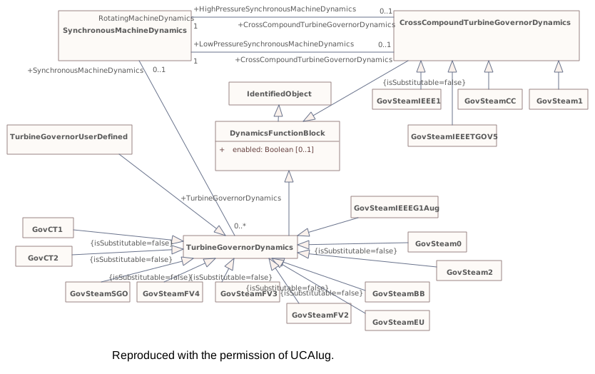
Destination
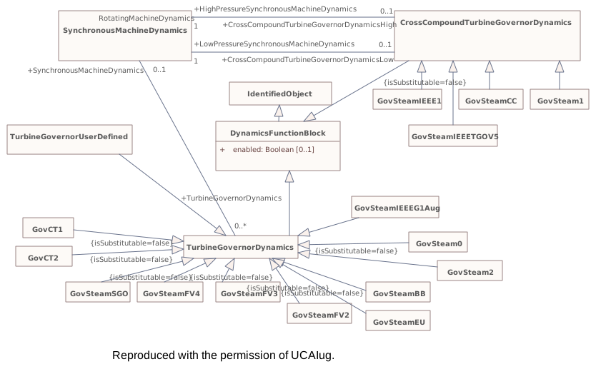
Connectors 2 labels changedhover a connector to outline the elements it joins
labels changedCrossCompoundTurbineGovernorDynamics – SynchronousMachineDynamicsrole name CrossCompoundTurbineGovernorDynamics → CrossCompoundTurbineGovernorDynamicsHigh
labels changedCrossCompoundTurbineGovernorDynamics – SynchronousMachineDynamicsrole name CrossCompoundTurbineGovernorDynamics → CrossCompoundTurbineGovernorDynamicsLow
▶TurbineLoadControllerDynamicsi
CHANGED{F0E43C7F-6E03-4b93-B0AF-2111023CA155}
Package notes
A turbine load controller acts to maintain turbine power at a set value by continuous adjustment of the turbine governor speed-load reference.Package metadata — changes
| Baseline | Destination | |
|---|---|---|
| no changes | ||
Tagged values — changes
| Baseline | Destination | |
|---|---|---|
| uri | http://iec.ch/TC57/CIM/TurbineLoadControllerDynamics/1.0 | http://ucaiug.org/CIM/TurbineLoadControllerDynamics/1.0 |
Package notes
A turbine load controller acts to maintain turbine power at a set value by continuous adjustment of the turbine governor speed-load reference.Tagged values
| Baseline | Destination | |
|---|---|---|
| uri | http://iec.ch/TC57/CIM/TurbineLoadControllerDynamics/1.0 | http://ucaiug.org/CIM/TurbineLoadControllerDynamics/1.0 |
Package 'TurbineLoadControllerDynamics' has no changes to the 2 classes it contains.
Package 'TurbineLoadControllerDynamics' has no changes to the 2 diagrams it contains.
▶MechanicalLoadDynamicsi
CHANGED{54ED4DD8-2593-43f5-9A32-43679D605D36}
Package notes
A mechanical load represents the variation in a motor's shaft torque or power as a function of shaft speed.Package metadata — changes
| Baseline | Destination | |
|---|---|---|
| no changes | ||
Tagged values — changes
| Baseline | Destination | |
|---|---|---|
| uri | http://iec.ch/TC57/CIM/MechanicalLoadDynamics/1.0 | http://ucaiug.org/CIM/MechanicalLoadDynamics/1.0 |
Package notes
A mechanical load represents the variation in a motor's shaft torque or power as a function of shaft speed.Tagged values
| Baseline | Destination | |
|---|---|---|
| uri | http://iec.ch/TC57/CIM/MechanicalLoadDynamics/1.0 | http://ucaiug.org/CIM/MechanicalLoadDynamics/1.0 |
Package 'MechanicalLoadDynamics' has no changes to the 2 classes it contains.
Package 'MechanicalLoadDynamics' has no changes to the 3 diagrams it contains.
▶ExcitationSystemDynamicsi
CHANGED{829F67E7-F698-4aa7-95C2-13C616AB6B78}
Package notes
The excitation system model provides the field voltage (<i>Efd</i>) for a synchronous machine model. It is linked to a specific generator (synchronous machine).
The representation of all limits used by the models (not including IEEE standard models) shall comply with the representation defined in Annex E of IEEE 421.5-2005, unless specified differently in the documentation of the model.
The parameters are different for each excitation system model; the same parameter name can have different meaning in different models.Package metadata — changes
| Baseline | Destination | |
|---|---|---|
| no changes | ||
Tagged values — changes
| Baseline | Destination | |
|---|---|---|
| uri | http://iec.ch/TC57/CIM/ExcitationSystemDynamics/1.0 | http://ucaiug.org/CIM/ExcitationSystemDynamics/1.0 |
Package notes
The excitation system model provides the field voltage (<i>Efd</i>) for a synchronous machine model. It is linked to a specific generator (synchronous machine).
The representation of all limits used by the models (not including IEEE standard models) shall comply with the representation defined in Annex E of IEEE 421.5-2005, unless specified differently in the documentation of the model.
The parameters are different for each excitation system model; the same parameter name can have different meaning in different models.Tagged values
| Baseline | Destination | |
|---|---|---|
| uri | http://iec.ch/TC57/CIM/ExcitationSystemDynamics/1.0 | http://ucaiug.org/CIM/ExcitationSystemDynamics/1.0 |
▶IEEE4215from2005i
CHANGED{D22779BB-015E-4250-9959-87234042A65F}
Package notes
Excitation system models from IEEE 421.5-2005.Package metadata — changes
| Baseline | Destination | |
|---|---|---|
| no changes | ||
Tagged values — changes
| Baseline | Destination | |
|---|---|---|
| uri | http://iec.ch/TC57/CIM/IEEE4215from2005/1.0 | http://ucaiug.org/CIM/IEEE4215from2005/1.0 |
Package notes
Excitation system models from IEEE 421.5-2005.Tagged values
| Baseline | Destination | |
|---|---|---|
| uri | http://iec.ch/TC57/CIM/IEEE4215from2005/1.0 | http://ucaiug.org/CIM/IEEE4215from2005/1.0 |
Package 'IEEE4215from2005' has no changes to the 20 classes it contains.
Package 'IEEE4215from2005' has no changes to the 1 diagrams it contains.
▶IEEE4215from2016i
CHANGED{1E5D2248-C621-443e-98E0-864F168D2479}
Package notes
Excitation system models from IEEE 421.5-2016.Package metadata — changes
| Baseline | Destination | |
|---|---|---|
| no changes | ||
Tagged values — changes
| Baseline | Destination | |
|---|---|---|
| uri | http://iec.ch/TC57/CIM/IEEE4215from2016/1.0 | http://ucaiug.org/CIM/IEEE4215from2016/1.0 |
Package notes
Excitation system models from IEEE 421.5-2016.Tagged values
| Baseline | Destination | |
|---|---|---|
| uri | http://iec.ch/TC57/CIM/IEEE4215from2016/1.0 | http://ucaiug.org/CIM/IEEE4215from2016/1.0 |
Package 'IEEE4215from2016' has no changes to the 31 classes it contains.
Package 'IEEE4215from2016' has no changes to the 1 diagrams it contains.
Package 'ExcitationSystemDynamics' has no changes to the 42 classes it contains.
Package 'ExcitationSystemDynamics' has no changes to the 39 diagrams it contains.
▶OverexcitationLimiterDynamicsi
CHANGED{CB5C7172-23DD-4cc0-ACF3-557E0496AFCD}
Package notes
Overexcitation limiters (OELs) are also referred to as <i>maximum excitation limiters </i>and <i>field current limiters. </i>The possibility of voltage collapse in stressed power systems increases the importance of modelling these limiters in studies of system conditions that cause machines to operate at high levels of excitation for a sustained period, such as voltage collapse or system-islanding. Such events typically occur over a long time frame compared with transient or small-signal stability simulations.Package metadata — changes
| Baseline | Destination | |
|---|---|---|
| no changes | ||
Tagged values — changes
| Baseline | Destination | |
|---|---|---|
| uri | http://iec.ch/TC57/CIM/OverexcitationLimiterDynamics/1.0 | http://ucaiug.org/CIM/OverexcitationLimiterDynamics/1.0 |
Package notes
Overexcitation limiters (OELs) are also referred to as <i>maximum excitation limiters </i>and <i>field current limiters. </i>The possibility of voltage collapse in stressed power systems increases the importance of modelling these limiters in studies of system conditions that cause machines to operate at high levels of excitation for a sustained period, such as voltage collapse or system-islanding. Such events typically occur over a long time frame compared with transient or small-signal stability simulations.Tagged values
| Baseline | Destination | |
|---|---|---|
| uri | http://iec.ch/TC57/CIM/OverexcitationLimiterDynamics/1.0 | http://ucaiug.org/CIM/OverexcitationLimiterDynamics/1.0 |
Package 'OverexcitationLimiterDynamics' has no changes to the 9 classes it contains.
Package 'OverexcitationLimiterDynamics' has no changes to the 6 diagrams it contains.
▶UnderexcitationLimiterDynamicsi
CHANGED{6601D8F5-D2D3-4743-A9D8-51CADC84A53A}
Package notes
Underexcitation limiters (UELs) act to boost excitation. The UEL typically senses either a combination of voltage and current of the synchronous machine or a combination of real and reactive power. Some UELs utilize a temperature or pressure recalibration feature, in which the UEL characteristic is shifted depending upon the generator cooling gas temperature or pressure.Package metadata — changes
| Baseline | Destination | |
|---|---|---|
| no changes | ||
Tagged values — changes
| Baseline | Destination | |
|---|---|---|
| uri | http://iec.ch/TC57/CIM/UnderexcitationLimiterDynamics/1.0 | http://ucaiug.org/CIM/UnderexcitationLimiterDynamics/1.0 |
Package notes
Underexcitation limiters (UELs) act to boost excitation. The UEL typically senses either a combination of voltage and current of the synchronous machine or a combination of real and reactive power. Some UELs utilize a temperature or pressure recalibration feature, in which the UEL characteristic is shifted depending upon the generator cooling gas temperature or pressure.Tagged values
| Baseline | Destination | |
|---|---|---|
| uri | http://iec.ch/TC57/CIM/UnderexcitationLimiterDynamics/1.0 | http://ucaiug.org/CIM/UnderexcitationLimiterDynamics/1.0 |
Package 'UnderexcitationLimiterDynamics' has no changes to the 7 classes it contains.
Package 'UnderexcitationLimiterDynamics' has no changes to the 4 diagrams it contains.
▶PowerSystemStabilizerDynamicsi
CHANGED{15788FE9-6C55-412c-8AB7-F3F1EB004BDF}
Package notes
The power system stabilizer (PSS) model provides an input (<i>Vs</i>) to the excitation system model to improve damping of system oscillations. A variety of input signals can be used depending on the particular design.Package metadata — changes
| Baseline | Destination | |
|---|---|---|
| no changes | ||
Tagged values — changes
| Baseline | Destination | |
|---|---|---|
| uri | http://iec.ch/TC57/CIM/PowerSystemStabilizerDynamics/1.0 | http://ucaiug.org/CIM/PowerSystemStabilizerDynamics/1.0 |
Package notes
The power system stabilizer (PSS) model provides an input (<i>Vs</i>) to the excitation system model to improve damping of system oscillations. A variety of input signals can be used depending on the particular design.Tagged values
| Baseline | Destination | |
|---|---|---|
| uri | http://iec.ch/TC57/CIM/PowerSystemStabilizerDynamics/1.0 | http://ucaiug.org/CIM/PowerSystemStabilizerDynamics/1.0 |
Package 'PowerSystemStabilizerDynamics' has no changes to the 26 classes it contains.
Package 'PowerSystemStabilizerDynamics' has no changes to the 16 diagrams it contains.
▶DiscontinuousExcitationControlDynamicsi
CHANGED{510FA576-60DA-4709-96D0-60C754D1875E}
Package notes
In certain system configurations, continuous excitation control with terminal voltage and power system stabilizing regulator input signals does not ensure that the potential of the excitation system for improving system stability is fully exploited. For these situations, discontinuous excitation control signals can be employed to enhance stability following large transient disturbances.
<font color="#0f0f0f">For additional information please refer to IEEE 421.5-2005, 12 and IEEE 421.5-2016, 14.</font>Package metadata — changes
| Baseline | Destination | |
|---|---|---|
| no changes | ||
Tagged values — changes
| Baseline | Destination | |
|---|---|---|
| uri | http://iec.ch/TC57/CIM/DiscontinuousExcitationControlDynamics/1.0 | http://ucaiug.org/CIM/DiscontinuousExcitationControlDynamics/1.0 |
Package notes
In certain system configurations, continuous excitation control with terminal voltage and power system stabilizing regulator input signals does not ensure that the potential of the excitation system for improving system stability is fully exploited. For these situations, discontinuous excitation control signals can be employed to enhance stability following large transient disturbances.
<font color="#0f0f0f">For additional information please refer to IEEE 421.5-2005, 12 and IEEE 421.5-2016, 14.</font>Tagged values
| Baseline | Destination | |
|---|---|---|
| uri | http://iec.ch/TC57/CIM/DiscontinuousExcitationControlDynamics/1.0 | http://ucaiug.org/CIM/DiscontinuousExcitationControlDynamics/1.0 |
Package 'DiscontinuousExcitationControlDynamics' has no changes to the 4 classes it contains.
Package 'DiscontinuousExcitationControlDynamics' has no changes to the 2 diagrams it contains.
▶PFVArControllerType1Dynamicsi
CHANGED{DB4B66D7-C753-481b-9C15-D0753561B765}
Package notes
<font color="#0f0f0f">Excitation systems for synchronous machines are sometimes supplied with an optional means of automatically adjusting generator output reactive power (VAr) or power factor (PF) to a user-specified value. This can be accomplished with either a reactive power or power factor controller or regulator. A reactive power or power factor controller is defined as a PF/VAr controller in IEEE 421.1 as “a control function that acts through the reference adjuster to modify the voltage regulator set point to maintain the synchronous machine steady-state power factor or reactive power at a predetermined value.”</font>
The signal excitation limiter status should come from the excitation systems.<font color="#0f0f0f"> </font>
<font color="#0f0f0f">For additional information please refer to IEEE 421.5-2005, 11 and IEEE 421.5-2016, 13.</font>Package metadata — changes
| Baseline | Destination | |
|---|---|---|
| no changes | ||
Tagged values — changes
| Baseline | Destination | |
|---|---|---|
| uri | http://iec.ch/TC57/CIM/PFVArControllerType1Dynamics/1.0 | http://ucaiug.org/CIM/PFVArControllerType1Dynamics/1.0 |
Package notes
<font color="#0f0f0f">Excitation systems for synchronous machines are sometimes supplied with an optional means of automatically adjusting generator output reactive power (VAr) or power factor (PF) to a user-specified value. This can be accomplished with either a reactive power or power factor controller or regulator. A reactive power or power factor controller is defined as a PF/VAr controller in IEEE 421.1 as “a control function that acts through the reference adjuster to modify the voltage regulator set point to maintain the synchronous machine steady-state power factor or reactive power at a predetermined value.”</font>
The signal excitation limiter status should come from the excitation systems.<font color="#0f0f0f"> </font>
<font color="#0f0f0f">For additional information please refer to IEEE 421.5-2005, 11 and IEEE 421.5-2016, 13.</font>Tagged values
| Baseline | Destination | |
|---|---|---|
| uri | http://iec.ch/TC57/CIM/PFVArControllerType1Dynamics/1.0 | http://ucaiug.org/CIM/PFVArControllerType1Dynamics/1.0 |
Package 'PFVArControllerType1Dynamics' has no changes to the 5 classes it contains.
Package 'PFVArControllerType1Dynamics' has no changes to the 1 diagrams it contains.
▶PFVArControllerType2Dynamicsi
CHANGED{9AF74EDB-FFF5-4083-A7D5-48644244A045}
Package notes
<font color="#0f0f0f">A var/pf regulator is defined as “a synchronous machine regulator that functions to maintain the power factor or reactive component of power at a predetermined value.” </font>
The signal excitation limiter status should come from the excitation systems
<font color="#0f0f0f">For additional information please refer to IEEE 421.5-2005, 11 and IEEE 421.5-2016, 13.</font>
<font color="#0f0f0f">
</font>Package metadata — changes
| Baseline | Destination | |
|---|---|---|
| no changes | ||
Tagged values — changes
| Baseline | Destination | |
|---|---|---|
| uri | http://iec.ch/TC57/CIM/PFVArControllerType2Dynamics/1.0 | http://ucaiug.org/CIM/PFVArControllerType2Dynamics/1.0 |
Package notes
<font color="#0f0f0f">A var/pf regulator is defined as “a synchronous machine regulator that functions to maintain the power factor or reactive component of power at a predetermined value.” </font>
The signal excitation limiter status should come from the excitation systems
<font color="#0f0f0f">For additional information please refer to IEEE 421.5-2005, 11 and IEEE 421.5-2016, 13.</font>
<font color="#0f0f0f">
</font>Tagged values
| Baseline | Destination | |
|---|---|---|
| uri | http://iec.ch/TC57/CIM/PFVArControllerType2Dynamics/1.0 | http://ucaiug.org/CIM/PFVArControllerType2Dynamics/1.0 |
Package 'PFVArControllerType2Dynamics' has no changes to the 6 classes it contains.
Package 'PFVArControllerType2Dynamics' has no changes to the 2 diagrams it contains.
▶VoltageAdjusterDynamicsi
CHANGED{35B78447-A031-4927-A915-5C69304A72D2}
Package notes
<font color="#0f0f0f">A voltage adjuster is a reference adjuster that uses inputs from a reactive power or power factor controller to modify the voltage regulator set point to maintain the synchronous machine steady-state power factor or reactive power at a predetermined value. </font>
<font color="#0f0f0f">For additional information please refer to IEEE 421.5-2005, 11.</font>Package metadata — changes
| Baseline | Destination | |
|---|---|---|
| no changes | ||
Tagged values — changes
| Baseline | Destination | |
|---|---|---|
| uri | http://iec.ch/TC57/CIM/VoltageAdjusterDynamics/1.0 | http://ucaiug.org/CIM/VoltageAdjusterDynamics/1.0 |
Package notes
<font color="#0f0f0f">A voltage adjuster is a reference adjuster that uses inputs from a reactive power or power factor controller to modify the voltage regulator set point to maintain the synchronous machine steady-state power factor or reactive power at a predetermined value. </font>
<font color="#0f0f0f">For additional information please refer to IEEE 421.5-2005, 11.</font>Tagged values
| Baseline | Destination | |
|---|---|---|
| uri | http://iec.ch/TC57/CIM/VoltageAdjusterDynamics/1.0 | http://ucaiug.org/CIM/VoltageAdjusterDynamics/1.0 |
Package 'VoltageAdjusterDynamics' has no changes to the 3 classes it contains.
Package 'VoltageAdjusterDynamics' has no changes to the 1 diagrams it contains.
▶VoltageCompensatorDynamicsi
CHANGED{7FD04580-1444-4ea3-A69D-D2D00000A4A9}
Package notes
<font color="#0f0f0f">Synchronous machine terminal voltage transducer and current compensator models</font> adjust the terminal voltage feedback to the excitation system by adding a quantity that is proportional to the terminal current of the generator. It is linked to a specific generator (synchronous machine).
<font color="#0f0f0f">Several types of compensation are available on most excitation systems. Synchronous machine active and reactive current compensation are the most common. Either reactive droop compensation and/or line-drop compensation can be used, simulating an impedance drop and effectively regulating at some point other than the terminals of the machine. The impedance or range of adjustment and type of compensation should be specified for different types. </font>
<font color="#0f0f0f">Care shall be taken to ensure that a consistent PU system is utilized for the compensator parameters and the synchronous machine current base.</font>
<font color="#0f0f0f">For further information see IEEE 421.5-2005, 4 and IEEE 421.5-2016, 5.</font>
<font color="#0f0f0f">
</font>Package metadata — changes
| Baseline | Destination | |
|---|---|---|
| no changes | ||
Tagged values — changes
| Baseline | Destination | |
|---|---|---|
| uri | http://iec.ch/TC57/CIM/VoltageCompensatorDynamics/1.0 | http://ucaiug.org/CIM/VoltageCompensatorDynamics/1.0 |
Package notes
<font color="#0f0f0f">Synchronous machine terminal voltage transducer and current compensator models</font> adjust the terminal voltage feedback to the excitation system by adding a quantity that is proportional to the terminal current of the generator. It is linked to a specific generator (synchronous machine).
<font color="#0f0f0f">Several types of compensation are available on most excitation systems. Synchronous machine active and reactive current compensation are the most common. Either reactive droop compensation and/or line-drop compensation can be used, simulating an impedance drop and effectively regulating at some point other than the terminals of the machine. The impedance or range of adjustment and type of compensation should be specified for different types. </font>
<font color="#0f0f0f">Care shall be taken to ensure that a consistent PU system is utilized for the compensator parameters and the synchronous machine current base.</font>
<font color="#0f0f0f">For further information see IEEE 421.5-2005, 4 and IEEE 421.5-2016, 5.</font>
<font color="#0f0f0f">
</font>Tagged values
| Baseline | Destination | |
|---|---|---|
| uri | http://iec.ch/TC57/CIM/VoltageCompensatorDynamics/1.0 | http://ucaiug.org/CIM/VoltageCompensatorDynamics/1.0 |
Package 'VoltageCompensatorDynamics' has no changes to the 4 classes it contains.
Package 'VoltageCompensatorDynamics' has no changes to the 2 diagrams it contains.
▶WindDynamicsi
CHANGED{6EA4C7E4-FDDC-4438-8A1C-12346215E0FA}
Package notes
Wind turbines are generally divided into four types, which are currently significant in power systems. The four types have the following characteristics:
- type 1: wind turbine with directly grid connected asynchronous generator with fixed rotor resistance (typically squirrel cage);
- type 2: wind turbine with directly grid connected asynchronous generator with variable rotor resistance;
- type 3: wind turbines with doubly-fed asynchronous generators (directly connected stator and rotor connected through power converter);
- type 4: wind turbines connected to the grid through a full size power converter.
Models included in this package are according to IEC 61400-27-1:2015.Package metadata — changes
| Baseline | Destination | |
|---|---|---|
| no changes | ||
Tagged values — changes
| Baseline | Destination | |
|---|---|---|
| uri | http://iec.ch/TC57/CIM/WindDynamics/1.0 | http://ucaiug.org/CIM/WindDynamics/1.0 |
Package notes
Wind turbines are generally divided into four types, which are currently significant in power systems. The four types have the following characteristics:
- type 1: wind turbine with directly grid connected asynchronous generator with fixed rotor resistance (typically squirrel cage);
- type 2: wind turbine with directly grid connected asynchronous generator with variable rotor resistance;
- type 3: wind turbines with doubly-fed asynchronous generators (directly connected stator and rotor connected through power converter);
- type 4: wind turbines connected to the grid through a full size power converter.
Models included in this package are according to IEC 61400-27-1:2015.Tagged values
| Baseline | Destination | |
|---|---|---|
| uri | http://iec.ch/TC57/CIM/WindDynamics/1.0 | http://ucaiug.org/CIM/WindDynamics/1.0 |
Package 'WindDynamics' has no changes to the 40 classes it contains.
Package 'WindDynamics' has no changes to the 4 diagrams it contains.
▶WindDynamicsEd2i
CHANGED{A1DAE49D-2659-4b0c-82A6-6983E3E745BF}
Package notes
Standard interconnections included in this package are according to IEC 61400-27-1:2020.
Wind turbines are generally divided into four types, which are currently significant in power systems. Although these models are designed for wind turbines according to IEC 61400-27-1:2020 some of them, e.g. Type 4A, can be used for modelling PV (photo voltaic) plants.
A dynamic model representing a type 1 wind turbine model (IEC 61400-27-1:2020, 6.2.2) uses asynchronous generators directly connected to the grid, i.e. without power converters. Most type 1 wind turbines have a soft-starter, but this is only active during start-up. There are two type 1 models:
- type 1A: wind turbines with fixed pitch angle;
- type 1B: wind turbines with under voltage ride-through pitch angle control.
A dynamic model representing a type 2 wind turbine model (IEC 61400-27-1:2020, 6.2.3) uses asynchronous machine in the static (power flow) model. The type 2 turbine is equipped with a variable rotor resistance and therefore uses a variable rotor resistance asynchronous generator. Type 2 wind turbines are also normally equipped with pitch control.
A dynamic model representing a type 3 wind turbine (IEC 61400-27-1:2020, 6.2.4) uses a doubly fed asynchronous generator, where the stator is directly connected to the grid and the rotor is connected through a back-to-back power converter.
A dynamic model representing a type 4 wind turbine (IEC 61400-27-1:2020, 6.2.5) which is connected to the grid through a full scale power converter. Type 4 wind turbines use either synchronous generators or asynchronous generators. Some type 4 wind turbines use direct drive synchronous generators, and therefore have no gearbox.
There are two type 4 models as follows:
- type 4A: a model neglecting the aerodynamic and mechanical parts and thus not simulating any power oscillations;
- type 4B: a model including a 2-mass mechanical model to replicate the power oscillations but assuming constant aerodynamic torque.Package metadata — changes
| Baseline | Destination | |
|---|---|---|
| no changes | ||
Tagged values — changes
| Baseline | Destination | |
|---|---|---|
| uri | http://iec.ch/TC57/CIM/WindDynamicsEd2/1.0 | http://ucaiug.org/CIM/WindDynamicsEd2/1.0 |
Package notes
Standard interconnections included in this package are according to IEC 61400-27-1:2020.
Wind turbines are generally divided into four types, which are currently significant in power systems. Although these models are designed for wind turbines according to IEC 61400-27-1:2020 some of them, e.g. Type 4A, can be used for modelling PV (photo voltaic) plants.
A dynamic model representing a type 1 wind turbine model (IEC 61400-27-1:2020, 6.2.2) uses asynchronous generators directly connected to the grid, i.e. without power converters. Most type 1 wind turbines have a soft-starter, but this is only active during start-up. There are two type 1 models:
- type 1A: wind turbines with fixed pitch angle;
- type 1B: wind turbines with under voltage ride-through pitch angle control.
A dynamic model representing a type 2 wind turbine model (IEC 61400-27-1:2020, 6.2.3) uses asynchronous machine in the static (power flow) model. The type 2 turbine is equipped with a variable rotor resistance and therefore uses a variable rotor resistance asynchronous generator. Type 2 wind turbines are also normally equipped with pitch control.
A dynamic model representing a type 3 wind turbine (IEC 61400-27-1:2020, 6.2.4) uses a doubly fed asynchronous generator, where the stator is directly connected to the grid and the rotor is connected through a back-to-back power converter.
A dynamic model representing a type 4 wind turbine (IEC 61400-27-1:2020, 6.2.5) which is connected to the grid through a full scale power converter. Type 4 wind turbines use either synchronous generators or asynchronous generators. Some type 4 wind turbines use direct drive synchronous generators, and therefore have no gearbox.
There are two type 4 models as follows:
- type 4A: a model neglecting the aerodynamic and mechanical parts and thus not simulating any power oscillations;
- type 4B: a model including a 2-mass mechanical model to replicate the power oscillations but assuming constant aerodynamic torque.Tagged values
| Baseline | Destination | |
|---|---|---|
| uri | http://iec.ch/TC57/CIM/WindDynamicsEd2/1.0 | http://ucaiug.org/CIM/WindDynamicsEd2/1.0 |
Package 'WindDynamicsEd2' has no changes to the 47 classes it contains.
Package 'WindDynamicsEd2' has no changes to the 4 diagrams it contains.
▶LoadDynamicsi
CHANGED{4B245477-75CE-4d8d-BBFE-0471D2D7A63D}
Package notes
Dynamic load models are used to represent the dynamic real and reactive load behaviour of a load from the static power flow model.
Dynamic load models can be defined as applying either to a single load (energy consumer) or to a group of energy consumers.
Large industrial motors or groups of similar motors can be represented by a synchronous machine model (SynchronousMachineDynamics) or an asynchronous machine model (AsynchronousMachineDynamics), which are usually represented as generators with negative active power output in the static (power flow) data.Package metadata — changes
| Baseline | Destination | |
|---|---|---|
| no changes | ||
Tagged values — changes
| Baseline | Destination | |
|---|---|---|
| uri | http://iec.ch/TC57/CIM/LoadDynamics/1.0 | http://ucaiug.org/CIM/LoadDynamics/1.0 |
Package notes
Dynamic load models are used to represent the dynamic real and reactive load behaviour of a load from the static power flow model.
Dynamic load models can be defined as applying either to a single load (energy consumer) or to a group of energy consumers.
Large industrial motors or groups of similar motors can be represented by a synchronous machine model (SynchronousMachineDynamics) or an asynchronous machine model (AsynchronousMachineDynamics), which are usually represented as generators with negative active power output in the static (power flow) data.Tagged values
| Baseline | Destination | |
|---|---|---|
| uri | http://iec.ch/TC57/CIM/LoadDynamics/1.0 | http://ucaiug.org/CIM/LoadDynamics/1.0 |
▶LoadCompositeWECCi
CHANGED{73C21E98-ADD0-4e8c-AA8C-D6A27FF9A1C8}
Package notes
WECC load composite model.Package metadata — changes
| Baseline | Destination | |
|---|---|---|
| no changes | ||
Tagged values — changes
| Baseline | Destination | |
|---|---|---|
| uri | http://iec.ch/TC57/CIM/LoadCompositeWECC/1.0 | http://ucaiug.org/CIM/LoadCompositeWECC/1.0 |
Package notes
WECC load composite model.Tagged values
| Baseline | Destination | |
|---|---|---|
| uri | http://iec.ch/TC57/CIM/LoadCompositeWECC/1.0 | http://ucaiug.org/CIM/LoadCompositeWECC/1.0 |
Package 'LoadCompositeWECC' has no changes to the 5 classes it contains.
Package 'LoadCompositeWECC' has no changes to the 1 diagrams it contains.
Package 'LoadDynamics' has no changes to the 8 classes it contains.
Package 'LoadDynamics' has no changes to the 6 diagrams it contains.
▶HVDCDynamicsi
CHANGED{7C62349B-D355-4ba0-BE12-91068427292A}
Package notes
High voltage direct current (HVDC) models.Package metadata — changes
| Baseline | Destination | |
|---|---|---|
| no changes | ||
Tagged values — changes
| Baseline | Destination | |
|---|---|---|
| uri | http://iec.ch/TC57/CIM/HVDCDynamics/1.0 | http://ucaiug.org/CIM/HVDCDynamics/1.0 |
Package notes
High voltage direct current (HVDC) models.Tagged values
| Baseline | Destination | |
|---|---|---|
| uri | http://iec.ch/TC57/CIM/HVDCDynamics/1.0 | http://ucaiug.org/CIM/HVDCDynamics/1.0 |
Package 'HVDCDynamics' has no changes to the 4 classes it contains.
Package 'HVDCDynamics' has no changes to the 1 diagrams it contains.
▶RelayDynamicsi
CHANGED{12DAD289-6717-49a7-BB2C-4F03C4AE9B63}
Package notes
Relay dynamics models.Package metadata — changes
| Baseline | Destination | |
|---|---|---|
| no changes | ||
Tagged values — changes
| Baseline | Destination | |
|---|---|---|
| uri | http://iec.ch/TC57/CIM/RelayDynamics/1.0 | http://ucaiug.org/CIM/RelayDynamics/1.0 |
Package notes
Relay dynamics models.Tagged values
| Baseline | Destination | |
|---|---|---|
| uri | http://iec.ch/TC57/CIM/RelayDynamics/1.0 | http://ucaiug.org/CIM/RelayDynamics/1.0 |
Package 'RelayDynamics' has no changes to the 3 classes it contains.
Package 'RelayDynamics' has no changes to the 1 diagrams it contains.
▶StatorCurrentLimiterDynamicsi
CHANGED{224F34BE-B5D0-488c-A176-A87196201ABE}
Package notes
A stator current limiter (SCL) can be used to prevent operation that would lead to overheating of the stator winding due to high stator currents. This might happen when system voltage significantly changes or turbine power is increased without an associated upgrade of the generator stator windings. It should be mentioned that the SCL can only reduce stator current by influencing excitation during operation with reactive stator current. Alternatively a tap change of the main transformer, if applicable, or a reduction of turbine power can be considered to reduce stator current.Package metadata — changes
| Baseline | Destination | |
|---|---|---|
| no changes | ||
Tagged values — changes
| Baseline | Destination | |
|---|---|---|
| uri | http://iec.ch/TC57/CIM/StatorCurrentLimiterDynamics/1.0 | http://ucaiug.org/CIM/StatorCurrentLimiterDynamics/1.0 |
Package notes
A stator current limiter (SCL) can be used to prevent operation that would lead to overheating of the stator winding due to high stator currents. This might happen when system voltage significantly changes or turbine power is increased without an associated upgrade of the generator stator windings. It should be mentioned that the SCL can only reduce stator current by influencing excitation during operation with reactive stator current. Alternatively a tap change of the main transformer, if applicable, or a reduction of turbine power can be considered to reduce stator current.Tagged values
| Baseline | Destination | |
|---|---|---|
| uri | http://iec.ch/TC57/CIM/StatorCurrentLimiterDynamics/1.0 | http://ucaiug.org/CIM/StatorCurrentLimiterDynamics/1.0 |
Package 'StatorCurrentLimiterDynamics' has no changes to the 3 classes it contains.
Package 'StatorCurrentLimiterDynamics' has no changes to the 1 diagrams it contains.
▶StaticVarCompensatorDynamicsi
CHANGED{97871C31-9D61-4b9b-A49A-F63A7DC2DBA5}
Package notes
Static var compensator (SVC) models.Package metadata — changes
| Baseline | Destination | |
|---|---|---|
| no changes | ||
Tagged values — changes
| Baseline | Destination | |
|---|---|---|
| uri | http://iec.ch/TC57/CIM/StaticVarCompensatorDynamics/1.0 | http://ucaiug.org/CIM/StaticVarCompensatorDynamics/1.0 |
Package notes
Static var compensator (SVC) models.Tagged values
| Baseline | Destination | |
|---|---|---|
| uri | http://iec.ch/TC57/CIM/StaticVarCompensatorDynamics/1.0 | http://ucaiug.org/CIM/StaticVarCompensatorDynamics/1.0 |
Package 'StaticVarCompensatorDynamics' has no changes to the 6 classes it contains.
Package 'StaticVarCompensatorDynamics' has no changes to the 1 diagrams it contains.
▶ShuntCompensatorDynamicsi
CHANGED{18A7B5F9-12C2-4073-A382-477CC64A3B54}
Package notes
Shunt compensator dynamics models.Package metadata — changes
| Baseline | Destination | |
|---|---|---|
| no changes | ||
Tagged values — changes
| Baseline | Destination | |
|---|---|---|
| uri | http://iec.ch/TC57/CIM/ShuntCompensatorDynamics/1.0 | http://ucaiug.org/CIM/ShuntCompensatorDynamics/1.0 |
Package notes
Shunt compensator dynamics models.Tagged values
| Baseline | Destination | |
|---|---|---|
| uri | http://iec.ch/TC57/CIM/ShuntCompensatorDynamics/1.0 | http://ucaiug.org/CIM/ShuntCompensatorDynamics/1.0 |
Changed classes (1)
▶⚙ShuntCompensatorDynamicsi
CHANGED{9336FB09-BE98-4dc7-93A7-AB0C51ADA46C}
Class notes (destination, redlined)
Shunt compensator whose behaviour is described by reference to a standard model <font color="#0f0f0f">or by definition of a user-defined model.</font>Class metadata — changes
| Baseline | Destination | |
|---|---|---|
| no changes | ||
Tagged values — changes
| Baseline | Destination | |
|---|---|---|
| no changes | ||
Class notes (destination, redlined)
Shunt compensator whose behaviour is described by reference to a standard model <font color="#0f0f0f">or by definition of a user-defined model.</font>⇄Links
CHANGEDAssociation{6FEFE937-CC2D-4e8b-866F-D70FC2C262B5}
BaselineShuntCompensatorDynamics role ShuntCompensatorDynamics [0..1] → ShuntCompensator role ShuntCompensator [0..1]
→
DestinationShuntCompensatorDynamics role ShuntCompensatorDynamics [0..1] → ShuntCompensator role ShuntCompensator [0..1]
Source end
no changes
Target end — ShuntCompensator
| Baseline | Destination | |
|---|---|---|
| RoleNote | Shunt compensato to which shunt compensator dynamics model applies. | Shunt |
Package 'ShuntCompensatorDynamics' has no changes to the 1 diagrams it contains.
▶StatcomDynamicsi
CHANGED{5AD5A535-9FB0-44fb-A314-694B39EEE13C}
Package notes
STATCOM models.Package metadata — changes
| Baseline | Destination | |
|---|---|---|
| no changes | ||
Tagged values — changes
| Baseline | Destination | |
|---|---|---|
| uri | http://iec.ch/TC57/CIM/StatcomDynamics/1.0 | http://ucaiug.org/CIM/StatcomDynamics/1.0 |
Package notes
STATCOM models.Tagged values
| Baseline | Destination | |
|---|---|---|
| uri | http://iec.ch/TC57/CIM/StatcomDynamics/1.0 | http://ucaiug.org/CIM/StatcomDynamics/1.0 |
Package 'StatcomDynamics' has no changes to the 2 classes it contains.
Package 'StatcomDynamics' has no changes to the 2 diagrams it contains.
▶WECCDynamicsi
CHANGED{979495FD-1EE1-43c7-879D-50024B1F055B}
Package notes
This subclause contains WECC dynamics models.Package metadata — changes
| Baseline | Destination | |
|---|---|---|
| no changes | ||
Tagged values — changes
| Baseline | Destination | |
|---|---|---|
| uri | http://iec.ch/TC57/CIM/WECCDynamics/1.0 | http://ucaiug.org/CIM/WECCDynamics/1.0 |
Package notes
This subclause contains WECC dynamics models.Tagged values
| Baseline | Destination | |
|---|---|---|
| uri | http://iec.ch/TC57/CIM/WECCDynamics/1.0 | http://ucaiug.org/CIM/WECCDynamics/1.0 |
Changed classes (3)
▶⚙WeccREECDi
CHANGED{4A54F837-22FE-4ff5-A9E9-217FE6A417F8}
Class notes
WECC PQ Controller and Current Limit Logic (REEC_D).
Reference: WECC REMWG, Proposal for new features for the renewable energy system generic models, 2021.Class metadata — changes
| Baseline | Destination | |
|---|---|---|
| no changes | ||
Tagged values — changes
| Baseline | Destination | |
|---|---|---|
| no changes | ||
Class notes
WECC PQ Controller and Current Limit Logic (REEC_D).
Reference: WECC REMWG, Proposal for new features for the renewable energy system generic models, 2021.≡Attributes
| Attribute | Baseline | Destination | Notes (destination, redlined) | ||||||||||||
|---|---|---|---|---|---|---|---|---|---|---|---|---|---|---|---|
| vcmpflagi{7C0F82C9-8B91-4c65-A48E-2F77D9B7BD6C}show details | Boolean [0..1] | Boolean [0..1] | |||||||||||||
Attribute notes (destination, redlined) Attribute metadata — changes
Tagged values — changes
| |||||||||||||||
▶⚙WeccREGCBi
CHANGED{68EE6160-914D-4e6f-BA7F-938C51D19207}
Class notes
WECC Generator/Converter model (REGC_B) which is an extension of the REGC_A model by changing the network interface between the generator/converter model from a current-source to a voltage-source.
Reference: WECC REMWG, Proposal for new features for the renewable energy system generic models, 2021.Class metadata — changes
| Baseline | Destination | |
|---|---|---|
| no changes | ||
Tagged values — changes
| Baseline | Destination | |
|---|---|---|
| no changes | ||
Class notes
WECC Generator/Converter model (REGC_B) which is an extension of the REGC_A model by changing the network interface between the generator/converter model from a current-source to a voltage-source.
Reference: WECC REMWG, Proposal for new features for the renewable energy system generic models, 2021.≡Attributes
| Attribute | Baseline | Destination | Notes (destination, redlined) | ||||||||||||
|---|---|---|---|---|---|---|---|---|---|---|---|---|---|---|---|
| pqflagi{B7D2F337-A45D-4e9d-8A4B-1120AA0F2277}show details | Boolean [0..1] | Boolean [0..1] | |||||||||||||
Attribute notes (destination, redlined) Attribute metadata — changes
Tagged values — changes
| |||||||||||||||
| rateFlagi{2E1E0FFE-AA60-48cb-874A-3BC97DC4C833}show details | Boolean [0..1] | Boolean [0..1] | |||||||||||||
Attribute notes (destination, redlined) Attribute metadata — changes
Tagged values — changes
| |||||||||||||||
▶⚙WeccREGCCi
CHANGED{AC53251F-392B-4146-9475-210CFB99436B}
Class notes
WECC Generator/Converter model (REGC_C) which is an alternative of the REGC_B model. This model is an advanced draft which is expected to be finalised by WECC.
Reference: WECC REMWG, Proposal for new features for the renewable energy system generic models, 2021.Class metadata — changes
| Baseline | Destination | |
|---|---|---|
| no changes | ||
Tagged values — changes
| Baseline | Destination | |
|---|---|---|
| no changes | ||
Class notes
WECC Generator/Converter model (REGC_C) which is an alternative of the REGC_B model. This model is an advanced draft which is expected to be finalised by WECC.
Reference: WECC REMWG, Proposal for new features for the renewable energy system generic models, 2021.≡Attributes
| Attribute | Baseline | Destination | Notes (destination, redlined) | ||||||||||||
|---|---|---|---|---|---|---|---|---|---|---|---|---|---|---|---|
| pqflagi{6F200A24-1E79-4f88-8220-5C583BBCACE6}show details | Boolean [0..1] | Boolean [0..1] | |||||||||||||
Attribute notes (destination, redlined) Attribute metadata — changes
Tagged values — changes
| |||||||||||||||
| rateFlagi{5F94CF46-B77C-4671-8D77-2E236FC8BC80}show details | Boolean [0..1] | Boolean [0..1] | |||||||||||||
Attribute notes (destination, redlined) Attribute metadata — changes
Tagged values — changes
| |||||||||||||||
| wmaxi{ADCC8761-F609-4c0d-8AE5-19AA7F24204A}show details | PU [0..1] | PU [0..1] | Upper limit on the PLL (wmax). | ||||||||||||
Attribute notes (destination, redlined) Upper limit on the PLL (wmax).Attribute metadata — changes
Tagged values — changes
| |||||||||||||||
| wmini{AFF83A41-1D5F-4607-909B-2E680A7761A2}show details | PU [0..1] | PU [0..1] | Lower limit on the PLL (wmin). | ||||||||||||
Attribute notes (destination, redlined) Lower limit on the PLL (wmin).Attribute metadata — changes
Tagged values — changes
| |||||||||||||||
Package 'WECCDynamics' has no changes to the 2 diagrams it contains.
▶IEEE1547Dynamicsi
CHANGED{A09B5CEC-743C-4cfb-B78F-2A74FA4B121D}
Package notes
This clause contains IEEE 1547-2018 dynamics models.
The IEEE 1547-2018 standard models advanced features on DER, like smart features to solar Photovoltaic (PV) inverters. Smart solar PV inverter features comprise, at minimum, the following: voltage ride-through, frequency ride-through, voltage support, frequency support, and ramp rates. Both voltage and frequency support can be achieved by various means. These features can minimize solar PV inverters generation potential negative impacts due to remote or local system grid events, voltage and/or frequency. The IEEE 1547-2018 standard enables new DER to have the capabilities for grid-supportive functionality, and the applicable authorities governing interconnection requirements can utilize these advanced features to provide more reliable and resilient energy to their customers as the power system continues to evolve. More details are available in the IEEE standard and IEEE Technical report PES-TR67.r1, 2020.Package metadata — changes
| Baseline | Destination | |
|---|---|---|
| no changes | ||
Tagged values — changes
| Baseline | Destination | |
|---|---|---|
| uri | http://iec.ch/TC57/CIM/IEEE1547Dynamics/1.0 | http://ucaiug.org/CIM/IEEE1547Dynamics/1.0 |
Package notes
This clause contains IEEE 1547-2018 dynamics models.
The IEEE 1547-2018 standard models advanced features on DER, like smart features to solar Photovoltaic (PV) inverters. Smart solar PV inverter features comprise, at minimum, the following: voltage ride-through, frequency ride-through, voltage support, frequency support, and ramp rates. Both voltage and frequency support can be achieved by various means. These features can minimize solar PV inverters generation potential negative impacts due to remote or local system grid events, voltage and/or frequency. The IEEE 1547-2018 standard enables new DER to have the capabilities for grid-supportive functionality, and the applicable authorities governing interconnection requirements can utilize these advanced features to provide more reliable and resilient energy to their customers as the power system continues to evolve. More details are available in the IEEE standard and IEEE Technical report PES-TR67.r1, 2020.Tagged values
| Baseline | Destination | |
|---|---|---|
| uri | http://iec.ch/TC57/CIM/IEEE1547Dynamics/1.0 | http://ucaiug.org/CIM/IEEE1547Dynamics/1.0 |
Package 'IEEE1547Dynamics' has no changes to the 18 classes it contains.
Package 'IEEE1547Dynamics' has no changes to the 1 diagrams it contains.
Package 'StandardModels' has no changes to the 2 classes it contains.
▶UserDefinedModelsi
CHANGED{93B7FCE7-E22B-45f5-81C9-BF67091B1825}
Package notes
This subclause contains user-defined dynamic model classes to support the exchange of both proprietary and explicitly defined user-defined models.
<u>Proprietary models</u> represent behaviour which, while not defined by a standard model class, is mutually understood by the sending and receiving applications based on the name passed in the .name attribute of the appropriate xxxUserDefined class. Proprietary model parameters are passed as general attributes using as many instances of the ProprietaryParameterDynamics class as there are parameters.
<u>Explicitly defined models</u> describe dynamic behaviour in detail in terms of control blocks and their input and output signals. Note that the classes to support explicitly defined modelling are not currently defined - it is future work intended to also be supported by the family of xxxUserDefined classes.
Both types of user-defined models use the family of xxxUserDefined classes, which allow a user-defined model to be used:
- as the model for an individual standard function block (such as a turbine-governor or power system stabilizer) in a standard interconnection model whose other function blocks could be either standard or user-defined. For an illustration of this form of usage for a proprietary model, see the ExampleFunctionBlockProprietaryModel diagram in Subclause 5.7.
- as the complete representation of a dynamic behaviour model (for an entire synchronous machine, for example) where standard function blocks and standard interconnections are not used at all. For an illustration of this form of usage for a proprietary model, see the ExampleCompleteProprietaryModel diagram in Subclause 5.7.Package metadata — changes
| Baseline | Destination | |
|---|---|---|
| no changes | ||
Tagged values — changes
| Baseline | Destination | |
|---|---|---|
| uri | http://iec.ch/TC57/CIM/UserDefinedModels/1.0 | http://ucaiug.org/CIM/UserDefinedModels/1.0 |
Package notes
This subclause contains user-defined dynamic model classes to support the exchange of both proprietary and explicitly defined user-defined models.
<u>Proprietary models</u> represent behaviour which, while not defined by a standard model class, is mutually understood by the sending and receiving applications based on the name passed in the .name attribute of the appropriate xxxUserDefined class. Proprietary model parameters are passed as general attributes using as many instances of the ProprietaryParameterDynamics class as there are parameters.
<u>Explicitly defined models</u> describe dynamic behaviour in detail in terms of control blocks and their input and output signals. Note that the classes to support explicitly defined modelling are not currently defined - it is future work intended to also be supported by the family of xxxUserDefined classes.
Both types of user-defined models use the family of xxxUserDefined classes, which allow a user-defined model to be used:
- as the model for an individual standard function block (such as a turbine-governor or power system stabilizer) in a standard interconnection model whose other function blocks could be either standard or user-defined. For an illustration of this form of usage for a proprietary model, see the ExampleFunctionBlockProprietaryModel diagram in Subclause 5.7.
- as the complete representation of a dynamic behaviour model (for an entire synchronous machine, for example) where standard function blocks and standard interconnections are not used at all. For an illustration of this form of usage for a proprietary model, see the ExampleCompleteProprietaryModel diagram in Subclause 5.7.Tagged values
| Baseline | Destination | |
|---|---|---|
| uri | http://iec.ch/TC57/CIM/UserDefinedModels/1.0 | http://ucaiug.org/CIM/UserDefinedModels/1.0 |
Package 'UserDefinedModels' has no changes to the 27 classes it contains.
Package 'UserDefinedModels' has no changes to the 1 diagrams it contains.
▶DetailedModelDescriptioni
CHANGED{253FE232-028A-4a6e-AA8F-420138B1EF38}
Package notes
This clause packages classes needed to describe a model for dynamics simulations. This approach enables parties to exchange user defined model description expressed as mathematical expressions. It can also be used to describe standard models. Different profiles that use this information model shall make a choice of language used to describe the equations. The model enables creation of two separate profiles:
1) a profile to describe the detailed model configuration, and
2) a profile to enable an exchange of parameters of the model described using profile defined in 1).Package metadata — changes
| Baseline | Destination | |
|---|---|---|
| no changes | ||
Tagged values — changes
| Baseline | Destination | |
|---|---|---|
| uri | http://iec.ch/TC57/CIM/DetailedModelDescription/1.0 | http://ucaiug.org/CIM/DetailedModelDescription/1.0 |
Package notes
This clause packages classes needed to describe a model for dynamics simulations. This approach enables parties to exchange user defined model description expressed as mathematical expressions. It can also be used to describe standard models. Different profiles that use this information model shall make a choice of language used to describe the equations. The model enables creation of two separate profiles:
1) a profile to describe the detailed model configuration, and
2) a profile to enable an exchange of parameters of the model described using profile defined in 1).Tagged values
| Baseline | Destination | |
|---|---|---|
| uri | http://iec.ch/TC57/CIM/DetailedModelDescription/1.0 | http://ucaiug.org/CIM/DetailedModelDescription/1.0 |
Changed classes (8)
▶⚙DetailedModelDescriptori
CHANGED{4AF9369A-AF00-49d7-8970-2B62B4AE1C8E}
Class notes
Describes different components of a detailed model.Class metadata — changes
| Baseline | Destination | |
|---|---|---|
| no changes | ||
Tagged values — changes
| Baseline | Destination | |
|---|---|---|
| no changes | ||
Class notes
Describes different components of a detailed model.⇄Links
CHANGEDGeneralization{DE5B8692-C605-47e8-852E-CD7C22EDA531}
BaselineParameterDesctiptor → DetailedModelDescriptor
→
Source end — ParameterDescriptor
| Baseline | Destination | |
|---|---|---|
| End | Parameter | Parameter |
Target end
no changes
▶⚙DetailedModelDescriptorArtifacti
CHANGED{7F8BCF76-2ABB-4457-AC02-292529023E0A}
Class notes
An artifact (e.g. file) describing the model. In can be used when reusing existing modules or in the use case where detailed models are already part of a reference library and the DetailedModelDynamics will only need to refer to a model from that library instead of constructing the model in detail.Class metadata — changes
| Baseline | Destination | |
|---|---|---|
| no changes | ||
Tagged values — changes
| Baseline | Destination | |
|---|---|---|
| no changes | ||
Class notes
An artifact (e.g. file) describing the model. In can be used when reusing existing modules or in the use case where detailed models are already part of a reference library and the DetailedModelDynamics will only need to refer to a model from that library instead of constructing the model in detail.≡Attributes
| Attribute | Baseline | Destination | Notes (destination, redlined) | ||||||||||||
|---|---|---|---|---|---|---|---|---|---|---|---|---|---|---|---|
| equationLanguageTypeOtheri{D3EB5EA1-8890-425e-A460-2BAB8BD580F7}show details | String [0..1] | String [0..1] | Defines the language used to describe equations. It is required if the attribute equationLanguageKind equals EquationLanguageKind.other. | ||||||||||||
Attribute notes (destination, redlined) Defines the language used to describe equations. It is required if the attribute equationLanguageKind equals EquationLanguageKind.other.Attribute metadata — changes
Tagged values — changes
| |||||||||||||||
▶⚙EquationLanguageKind«enumeration»i
CHANGED{8A20297E-EAE9-46aa-BEC1-E5E2041F48F7}
Class notes
Kinds of languages defined for describing an equation.Class metadata — changes
| Baseline | Destination | |
|---|---|---|
| no changes | ||
Tagged values — changes
| Baseline | Destination | |
|---|---|---|
| no changes | ||
Class notes
Kinds of languages defined for describing an equation.≡Attributes
| Attribute | Baseline | Destination | Notes (destination, redlined) | ||||||||||||||||||||||||||||||||||||||||||||||||
|---|---|---|---|---|---|---|---|---|---|---|---|---|---|---|---|---|---|---|---|---|---|---|---|---|---|---|---|---|---|---|---|---|---|---|---|---|---|---|---|---|---|---|---|---|---|---|---|---|---|---|---|
| otheri{0412DBE5-FD83-4dda-855D-16F4288AB6C8}show details | did not exist | [1..1] | Other language used to express the equation. | ||||||||||||||||||||||||||||||||||||||||||||||||
Attribute notes Other language used to express the equation.Attribute metadata — changes
Tagged values — changes
| |||||||||||||||||||||||||||||||||||||||||||||||||||
▶⚙FunctionDescriptori
CHANGED{FCE28F14-8174-451c-9EC9-F6894CFFB921}
Class notes
Describes a function part of the detailed model.Class metadata — changes
| Baseline | Destination | |
|---|---|---|
| no changes | ||
Tagged values — changes
| Baseline | Destination | |
|---|---|---|
| no changes | ||
Class notes
Describes a function part of the detailed model.⇄Links
CHANGEDAssociation{97D81216-EF8E-4cb4-8978-54194A4204C2}
BaselineFunctionDescriptor role FunctionDescriptor [0..*] → ParameterDesctiptor role ParameterDescriptor [0..*]
→
DestinationFunctionDescriptor role FunctionDescriptor [0..*] → ParameterDescriptor role ParameterDescriptor [0..*]
Source end
no changes
Target end — ParameterDescriptor
| Baseline | Destination | |
|---|---|---|
| End | Parameter | Parameter |
▶⚙ParameterDescriptorrenamed from ParameterDesctiptori
CHANGED{5C8F98A8-A6B9-495f-A1F9-200AF31D1E84}
Class notes
Supports definition of one or more parameters of several different datatypes for use by the detailed model. It describes the parameters used in the equations of the detailed model.
The name of the parameter shall be the same as the name used in the equations of the detailed model.Class metadata — changes
| Baseline | Destination | |
|---|---|---|
| Name | ParameterDesctiptor | ParameterDescriptor |
Tagged values — changes
| Baseline | Destination | |
|---|---|---|
| no changes | ||
Class notes
Supports definition of one or more parameters of several different datatypes for use by the detailed model. It describes the parameters used in the equations of the detailed model.
The name of the parameter shall be the same as the name used in the equations of the detailed model.▤Metadata
| Baseline | Destination | |
|---|---|---|
| Name | ParameterDesctiptor | ParameterDescriptor |
⇄Links
CHANGEDGeneralization{DE5B8692-C605-47e8-852E-CD7C22EDA531}
BaselineParameterDesctiptor → DetailedModelDescriptor
→
Source end — ParameterDescriptor
| Baseline | Destination | |
|---|---|---|
| End | Parameter | Parameter |
Target end
no changes
CHANGEDAssociation{97D81216-EF8E-4cb4-8978-54194A4204C2}
BaselineFunctionDescriptor role FunctionDescriptor [0..*] → ParameterDesctiptor role ParameterDescriptor [0..*]
→
DestinationFunctionDescriptor role FunctionDescriptor [0..*] → ParameterDescriptor role ParameterDescriptor [0..*]
Source end
no changes
Target end — ParameterDescriptor
| Baseline | Destination | |
|---|---|---|
| End | Parameter | Parameter |
CHANGEDAssociation{9D6B2D40-EB75-4d47-B226-6D4129EF3D65}
BaselineParameterValue role ParameterValue [0..*] → ParameterDesctiptor role ParameterDescriptor [0..1]
→
DestinationParameterValue role ParameterValue [0..*] → ParameterDescriptor role ParameterDescriptor [0..1]
Source end
no changes
Target end — ParameterDescriptor
| Baseline | Destination | |
|---|---|---|
| End | Parameter | Parameter |
▶⚙ParameterValuei
CHANGED{935A7CF0-CF83-4253-BAED-FA7AD85B3D2B}
Class notes
Provides the value of a given parameter of a detailed model dynamics.Class metadata — changes
| Baseline | Destination | |
|---|---|---|
| no changes | ||
Tagged values — changes
| Baseline | Destination | |
|---|---|---|
| no changes | ||
Class notes
Provides the value of a given parameter of a detailed model dynamics.⇄Links
CHANGEDAssociation{9D6B2D40-EB75-4d47-B226-6D4129EF3D65}
BaselineParameterValue role ParameterValue [0..*] → ParameterDesctiptor role ParameterDescriptor [0..1]
→
DestinationParameterValue role ParameterValue [0..*] → ParameterDescriptor role ParameterDescriptor [0..1]
Source end
no changes
Target end — ParameterDescriptor
| Baseline | Destination | |
|---|---|---|
| End | Parameter | Parameter |
▶⚙SignalDescriptori
CHANGED{2DD8FECD-752D-4663-AC1B-97BCE547731A}
Class notes
Describes the signals both internal signals that connect different functions or external signals.Class metadata — changes
| Baseline | Destination | |
|---|---|---|
| no changes | ||
Tagged values — changes
| Baseline | Destination | |
|---|---|---|
| no changes | ||
Class notes
Describes the signals both internal signals that connect different functions or external signals.⇄Links
CHANGEDAssociation{61C72648-1B2B-4ebb-ABD7-BD93DFF34E44}
→
Source end
no changes
Target end — ACDCTerminal
| Baseline | Destination | |
|---|---|---|
| RoleNote | Th eterminal for this signal descriptor. |
▶⚙XSDDatatypeKind«enumeration»i
CHANGED{268029F8-16D6-4ea7-9C24-AA49ECE72615}
Class notes
The XSD datatypes kinds.Class metadata — changes
| Baseline | Destination | |
|---|---|---|
| no changes | ||
Tagged values — changes
| Baseline | Destination | |
|---|---|---|
| no changes | ||
Class notes
The XSD datatypes kinds.≡Attributes
| Attribute | Baseline | Destination | Notes (destination, redlined) | ||||||||||||||||||||||||||||||||||||||||||||||||
|---|---|---|---|---|---|---|---|---|---|---|---|---|---|---|---|---|---|---|---|---|---|---|---|---|---|---|---|---|---|---|---|---|---|---|---|---|---|---|---|---|---|---|---|---|---|---|---|---|---|---|---|
| integeri{2E69C9DF-19CC-429b-8C2D-E8FFB1AA31E6}show details | did not exist | [1..1] | Integer is derived from decimal by fixing the value of fraction digits to be 0 and disallowing the trailing decimal point. This results in the standard mathematical concept of the integer numbers. The value space of integer is the infinite set {...,-2,-1,0,1,2,...}, [W3C Recommendation, XML Schema Definition Language (XSD) 1.1 Part 2: Datatypes, 5 April 2012]. | ||||||||||||||||||||||||||||||||||||||||||||||||
Attribute notes Integer is derived from decimal by fixing the value of fraction digits to be 0 and disallowing the trailing decimal point. This results in the standard mathematical concept of the integer numbers. The value space of integer is the infinite set {...,-2,-1,0,1,2,...}, [W3C Recommendation, XML Schema Definition Language (XSD) 1.1 Part 2: Datatypes, 5 April 2012].Attribute metadata — changes
Tagged values — changes
| |||||||||||||||||||||||||||||||||||||||||||||||||||
Changed diagrams (1)
▶▦DetailedModelDescriptioni
CHANGED{25C584F8-6BE5-4947-9DEB-059BA8F93CBC}
Diagram notes
The diagram presents the classes used in the detailed model description approach of exchange dynamics models.Diagram metadata — changes
| Baseline | Destination | |
|---|---|---|
| ModifiedDate | 2022-03-18 21:39:45 | 2023-02-06 21:21:04 |
Diagram notes
The diagram presents the classes used in the detailed model description approach of exchange dynamics models.▤Metadata
| Baseline | Destination | |
|---|---|---|
| ModifiedDate | 2022-03-18 21:39:45 | 2023-02-06 21:21:04 |
▦Diagram
removedchanged
Baseline
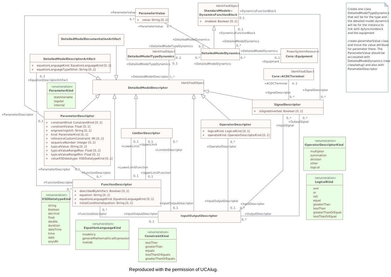
Destination
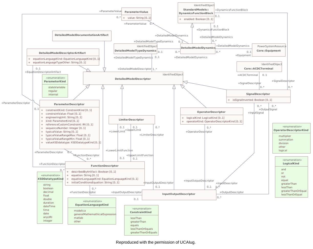
Connectors 1 reroutedhover a connector to outline the elements it joins
reroutedSignalDescriptor – ACDCTerminal
▶SimulationResulti
CHANGED{F46BFE09-1F7D-4908-90ED-4A9799CF92B0}
Package notes
This clause contains classes needed to describe dynamics simulation settings and results.Package metadata — changes
| Baseline | Destination | |
|---|---|---|
| no changes | ||
Tagged values — changes
| Baseline | Destination | |
|---|---|---|
| uri | http://iec.ch/TC57/CIM/SimulationResult/1.0 | http://ucaiug.org/CIM/SimulationResult/1.0 |
Package notes
This clause contains classes needed to describe dynamics simulation settings and results.Tagged values
| Baseline | Destination | |
|---|---|---|
| uri | http://iec.ch/TC57/CIM/SimulationResult/1.0 | http://ucaiug.org/CIM/SimulationResult/1.0 |
Changed classes (2)
▶⚙SignalRecorderi
CHANGED{8C8B07AB-3ABA-48cd-AD41-6CDBC9144776}
Class notes
A recorder for a given signal.Class metadata — changes
| Baseline | Destination | |
|---|---|---|
| no changes | ||
Tagged values — changes
| Baseline | Destination | |
|---|---|---|
| no changes | ||
Class notes
A recorder for a given signal.⇄Links
CHANGEDAssociation{17CC34C3-D3E4-42ee-AD6B-BA5A83E31253}
BaselineSignalRecorder role y1valueSignal [1] → SimulationResultCharacteristic role SimulationCharacteristic1 [0..1]
→
DestinationSignalRecorder role y1valueSignalY1valueSignal [1] → SimulationResultCharacteristic role SimulationCharacteristic1 [0..1]
Source end — Y1valueSignal
| Baseline | Destination | |
|---|---|---|
| Role | y1value | Y1value |
Target end
no changes
CHANGEDAssociation{6D111ADA-16AC-468e-9157-13EABCD7DF8A}
BaselineSignalRecorder role y3valueSignal [0..1] → SimulationResultCharacteristic role SimulationCharacteristic3 [0..1]
→
DestinationSignalRecorder role y3valueSignalY3valueSignal [0..1] → SimulationResultCharacteristic role SimulationCharacteristic3 [0..1]
Source end — Y3valueSignal
| Baseline | Destination | |
|---|---|---|
| Role | y3value | Y3value |
Target end
no changes
CHANGEDAssociation{8BB7B6F0-1C56-4359-81E9-92BAFE6933BC}
BaselineSignalRecorder role y2valueSignal [0..1] → SimulationResultCharacteristic role SimulationChacteristic2 [0..1]
→
DestinationSignalRecorder role y2valueSignalY2valueSignal [0..1] → SimulationResultCharacteristic role SimulationChacteristic2 [0..1]
Source end — Y2valueSignal
| Baseline | Destination | |
|---|---|---|
| Role | y2value | Y2value |
Target end
no changes
▶⚙SimulationResultCharacteristici
CHANGED{6EEE5489-6B1B-409b-8E16-26AFCCA3F530}
Class notes
Result characteristic. The xvalue of the curve is time.Class metadata — changes
| Baseline | Destination | |
|---|---|---|
| no changes | ||
Tagged values — changes
| Baseline | Destination | |
|---|---|---|
| no changes | ||
Class notes
Result characteristic. The xvalue of the curve is time.⇄Links
CHANGEDAssociation{17CC34C3-D3E4-42ee-AD6B-BA5A83E31253}
BaselineSignalRecorder role y1valueSignal [1] → SimulationResultCharacteristic role SimulationCharacteristic1 [0..1]
→
DestinationSignalRecorder role y1valueSignalY1valueSignal [1] → SimulationResultCharacteristic role SimulationCharacteristic1 [0..1]
Source end — Y1valueSignal
| Baseline | Destination | |
|---|---|---|
| Role | y1value | Y1value |
Target end
no changes
CHANGEDAssociation{6D111ADA-16AC-468e-9157-13EABCD7DF8A}
BaselineSignalRecorder role y3valueSignal [0..1] → SimulationResultCharacteristic role SimulationCharacteristic3 [0..1]
→
DestinationSignalRecorder role y3valueSignalY3valueSignal [0..1] → SimulationResultCharacteristic role SimulationCharacteristic3 [0..1]
Source end — Y3valueSignal
| Baseline | Destination | |
|---|---|---|
| Role | y3value | Y3value |
Target end
no changes
CHANGEDAssociation{8BB7B6F0-1C56-4359-81E9-92BAFE6933BC}
BaselineSignalRecorder role y2valueSignal [0..1] → SimulationResultCharacteristic role SimulationChacteristic2 [0..1]
→
DestinationSignalRecorder role y2valueSignalY2valueSignal [0..1] → SimulationResultCharacteristic role SimulationChacteristic2 [0..1]
Source end — Y2valueSignal
| Baseline | Destination | |
|---|---|---|
| Role | y2value | Y2value |
Target end
no changes
Changed diagrams (1)
▶▦SimulationResulti
CHANGED{3B18EC92-2D46-4747-85A5-7D1957304C6D}
Diagram notes
The diagram presents the classes used in the part of the model used to exchange dynamics simulation results.Diagram metadata — changes
| Baseline | Destination | |
|---|---|---|
| ModifiedDate | 2022-03-18 21:39:30 | 2023-02-11 12:39:01 |
Diagram notes
The diagram presents the classes used in the part of the model used to exchange dynamics simulation results.▤Metadata
| Baseline | Destination | |
|---|---|---|
| ModifiedDate | 2022-03-18 21:39:30 | 2023-02-11 12:39:01 |
▦Diagram
Baseline
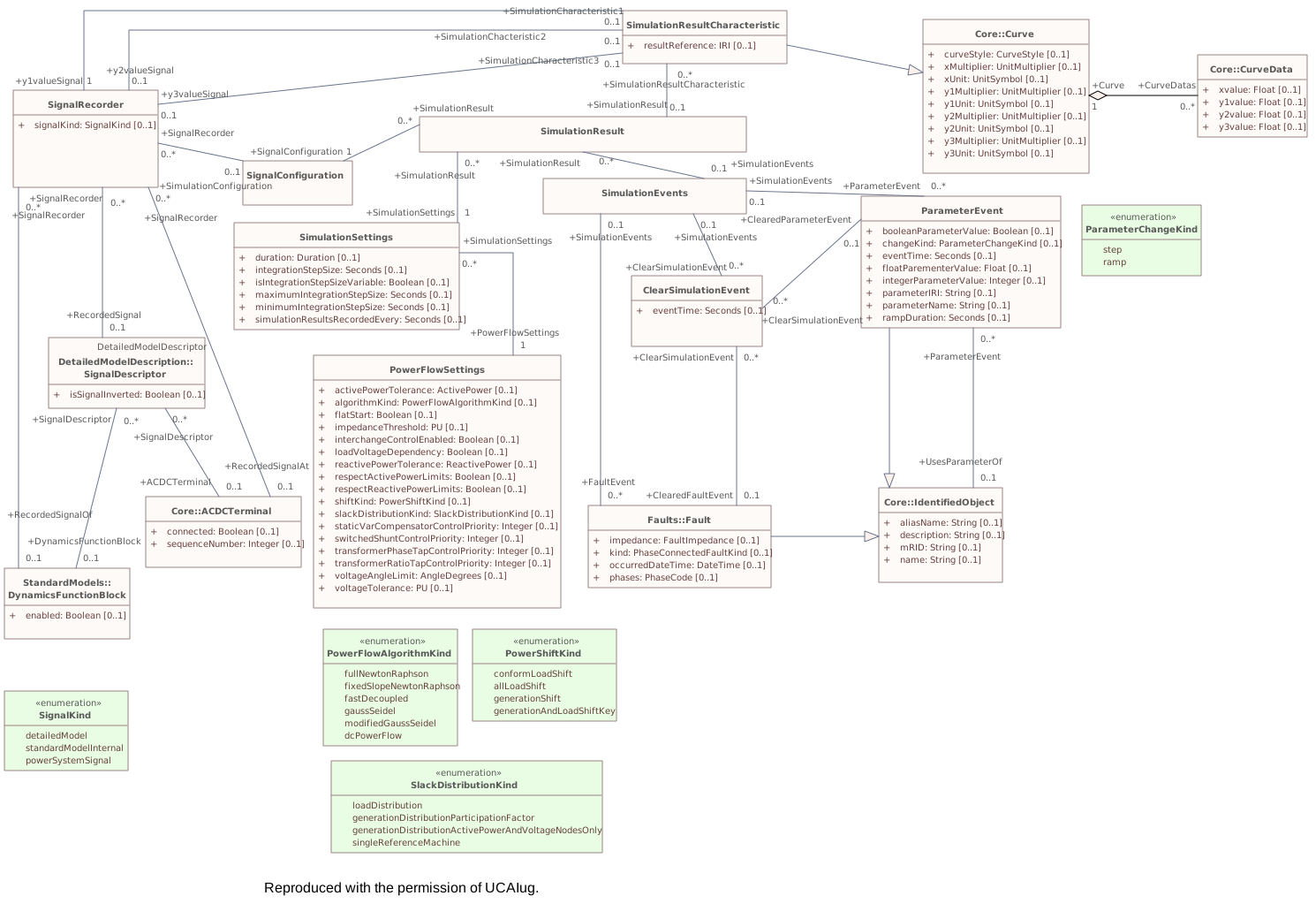
Destination
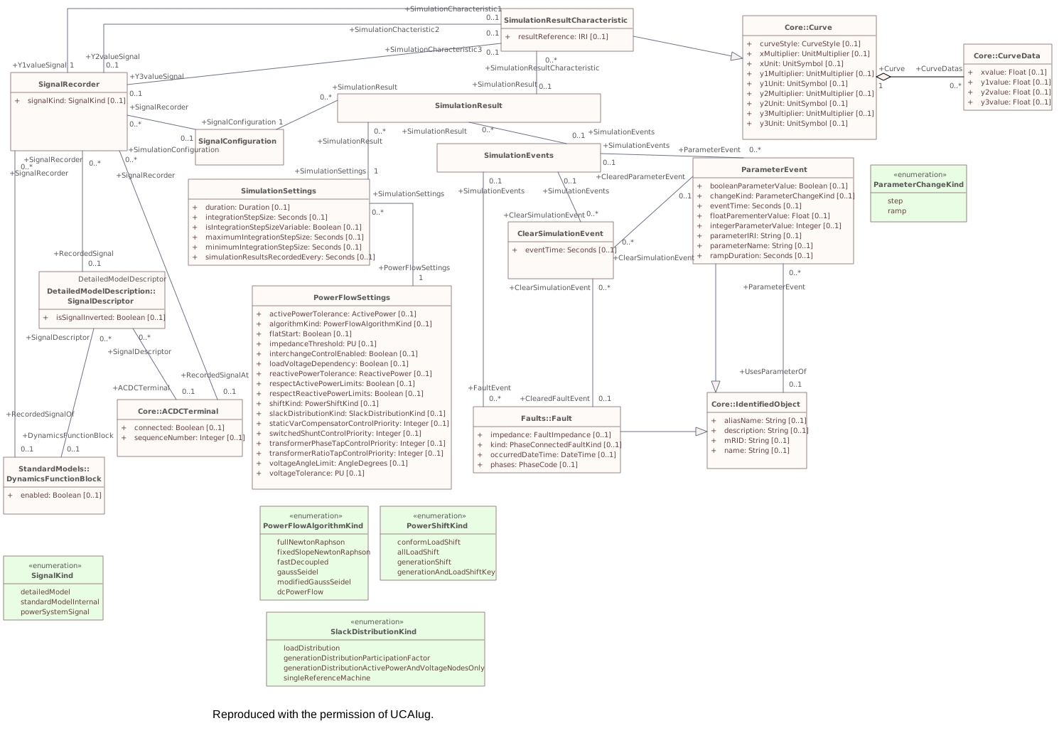
Connectors 1 rerouted · 2 labels changedhover a connector to outline the elements it joins
reroutedSignalRecorder – SimulationResultCharacteristic
labels changedSignalRecorder – SimulationResultCharacteristicrole name y1valueSignal → Y1valueSignal
labels changedSignalRecorder – SimulationResultCharacteristicrole name y2valueSignal → Y2valueSignal
▶Examplesi
CHANGED{A2D0E510-CA3E-4314-B55C-29C4F3D051A0}
Package notes
Examples illustrating the use of dynamic behaviour models are given in the following diagrams.Package metadata — changes
| Baseline | Destination | |
|---|---|---|
| no changes | ||
Tagged values — changes
| Baseline | Destination | |
|---|---|---|
| uri | http://iec.ch/TC57/CIM/Examples/1.0 | http://ucaiug.org/CIM/Examples/1.0 |
Package notes
Examples illustrating the use of dynamic behaviour models are given in the following diagrams.Tagged values
| Baseline | Destination | |
|---|---|---|
| uri | http://iec.ch/TC57/CIM/Examples/1.0 | http://ucaiug.org/CIM/Examples/1.0 |
Package 'Examples' has no changes to the 3 diagrams it contains.
▶InfGridrenamed from InfIEC61970iWG13It doesshould not be used to generate any formal documentation foras this is an informative portion of the model.
CHANGED{D2DD87AA-AF0C-477c-8E65-69D543D76521}
Package notes (destination, redlined)
This package and its subpackages contain informative (unstable) elements of the model, expected to evolve a lot or to be removed, and not published as IEC document yet. Some portions of it will be reworked and moved to normative packages as the need arises, and some portions may be removed.
Package metadata — changes
| Baseline | Destination | |
|---|---|---|
| Name | InfIEC61970 | InfGrid |
Tagged values — changes
| Baseline | Destination | |
|---|---|---|
| no changes | ||
Package notes (destination, redlined)
This package and its subpackages contain informative (unstable) elements of the model, expected to evolve a lot or to be removed, and not published as IEC document yet. Some portions of it will be reworked and moved to normative packages as the need arises, and some portions may be removed.
Changed diagrams (1)
▶▦InfIEC61970Dependenciesi
CHANGED{7730AA1F-77BF-4755-87D0-FCF3496ADBB1}
Diagram notes
This diagram shows all 61970 packages and their logical dependencies. Note that the sub-packages under Dynamics package are not shown.Diagram metadata — changes
| Baseline | Destination | |
|---|---|---|
| ParentPackage | InfIEC61970 | InfGrid |
Diagram notes
This diagram shows all 61970 packages and their logical dependencies. Note that the sub-packages under Dynamics package are not shown.▤Metadata
| Baseline | Destination | |
|---|---|---|
| ParentPackage | InfIEC61970 | InfGrid |
Diagram 'InfIEC61970Dependencies' has no other changes. The shows its notes and every changed property.
Changed classes (1)
▶⚙GridCIMVersionrenamed from IEC61970CIMVersioniThis is the IEC 61970 CIM version number assigned to this UML model. This is the release version number assigned to Grid part of the CIM model. It is a point-in-time snapshot of the state of the CIM UML model that reflects a formal release of the CIM. This release version is distinct from the unique version (e.g. http://ucaiug.org/CIM/Base/1.0) associated with each package in the UML.
CHANGED{990AB50C-5CF8-46d2-B5FF-887BBBD3346F}
Class notes (destination, redlined)
Class metadata — changes
| Baseline | Destination | |
|---|---|---|
| Name | IEC61970CIMVersion | GridCIMVersion |
| ParentPackage | IEC61970 | Grid |
Tagged values — changes
| Baseline | Destination | |
|---|---|---|
| no changes | ||
Class notes (destination, redlined)
▤Metadata
| Baseline | Destination | |
|---|---|---|
| Name | IEC61970CIMVersion | GridCIMVersion |
| ParentPackage | IEC61970 | Grid |
≡Attributes
| Attribute | Baseline | Destination | Notes (destination, redlined) | ||||||||||||
|---|---|---|---|---|---|---|---|---|---|---|---|---|---|---|---|
| dateimetadata changed - hovermetadata changed{8DADB97F-283D-40c7-A25A-D75E4C0D8507}show details | Date [0..1] | Date [0..1] | Form is YYYY-MM-DD for example for January 5, 2009 it is 2009-01-05. | ||||||||||||
Attribute notes Form is YYYY-MM-DD for example for January 5, 2009 it is 2009-01-05.Attribute metadata — changes
Tagged values — changes
| |||||||||||||||
| versionimetadata changed - hovermetadata changed{B4E0B1B6-8794-406a-A4C6-CBB395E37A52}show details | String [0..1] | String [0..1] | Form is | ||||||||||||
Attribute notes (destination, redlined) Form is Attribute metadata — changes
Tagged values — changes
| |||||||||||||||
Changed diagrams (1)
▶▦BaseDependenciesrenamed from IEC61970Dependenciesi61970-301base packages and their logical dependencies.
CHANGED{FB07D92D-5F4D-4fdc-AD82-2376FAF51037}
Diagram notes (destination, redlined)
This diagram shows all Diagram metadata — changes
| Baseline | Destination | |
|---|---|---|
| ModifiedDate | 2022-06-10 12:25:44 | 2023-02-07 22:43:55 |
| Name | IEC61970Dependencies | BaseDependencies |
| ParentPackage | IEC61970 | Grid |
Diagram notes (destination, redlined)
This diagram shows all ▤Metadata
| Baseline | Destination | |
|---|---|---|
| ModifiedDate | 2022-06-10 12:25:44 | 2023-02-07 22:43:55 |
| Name | IEC61970Dependencies | BaseDependencies |
| ParentPackage | IEC61970 | Grid |
▦Diagram
removed
Baseline
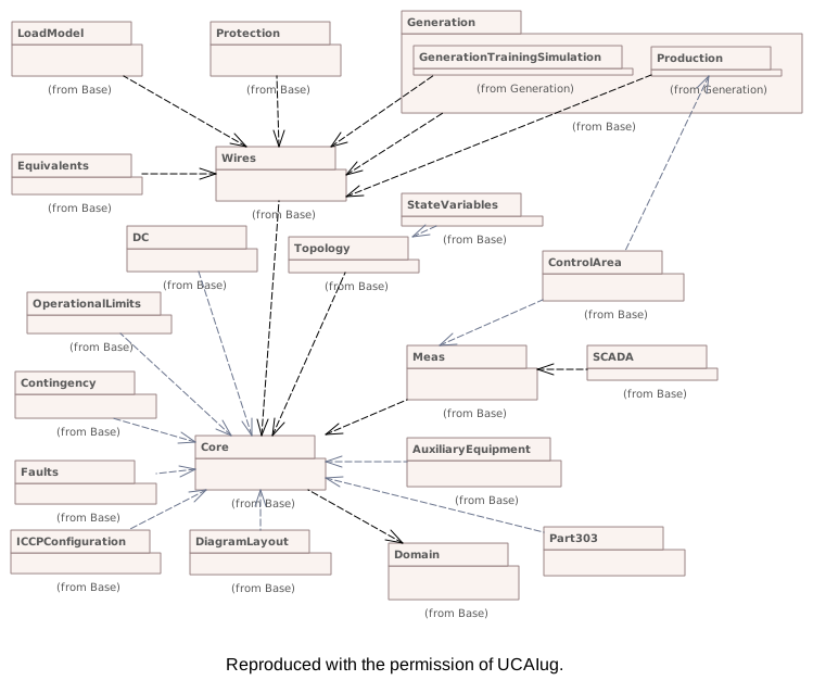
Destination
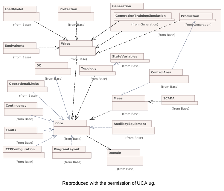
Connectors 1 removedhover a connector to outline the elements it joins
removed(not in this model) – (not in this model)