Packages1 moved
Classes24 changed
Diagrams43 changed
Click a count to show only those itemspAdded — only in destinationDeleted — only in baselineMoved — same GUID, different packageChanged — same GUID and package; properties or members differIdenticalPackage (unchanged itself)struckinserted — destination text with baseline wording struck (notes, role notes, role names, multiplicities); the shows the notes and every changed propertyBlue — a changed attribute type (the new type)
▶IEC61970i
{21D32832-FF64-4213-B81C-55ACE35EEBFF}
Package notes
Top package for IEC 61970.Package metadata — changes
| Baseline | Destination | |
|---|---|---|
| no changes | ||
Tagged values — changes
| Baseline | Destination | |
|---|---|---|
| no changes | ||
Package notes
Top package for IEC 61970.▶Basei
{20A2C6D8-4765-466f-AD75-5E1B3CAF4E8D}
Package notes
Content of the base CIM published as IEC 61970-301.Package metadata — changes
| Baseline | Destination | |
|---|---|---|
| no changes | ||
Tagged values — changes
| Baseline | Destination | |
|---|---|---|
| no changes | ||
Package notes
Content of the base CIM published as IEC 61970-301.▶Corei
{6A503B72-6E15-4cd1-B92D-DDF6D14DBE29}
Package notes
Contains the core PowerSystemResource and ConductingEquipment entities shared by all applications plus common collections of those entities. Not all applications require all the Core entities. This package does not depend on any other package except the Domain package, but most of the other packages have associations and generalizations that depend on it.Package metadata — changes
| Baseline | Destination | |
|---|---|---|
| no changes | ||
Tagged values — changes
| Baseline | Destination | |
|---|---|---|
| no changes | ||
Package notes
Contains the core PowerSystemResource and ConductingEquipment entities shared by all applications plus common collections of those entities. Not all applications require all the Core entities. This package does not depend on any other package except the Domain package, but most of the other packages have associations and generalizations that depend on it.Changed classes (9)
▶⚙ConductingEquipmenti
CHANGED{7C5F19FB-5253-430c-8E53-BDCF7EBCE4C1}
Class notes
The parts of the AC power system that are designed to carry current or that are conductively connected through terminals.Class metadata — changes
| Baseline | Destination | |
|---|---|---|
| no changes | ||
Tagged values — changes
| Baseline | Destination | |
|---|---|---|
| no changes | ||
Class notes
The parts of the AC power system that are designed to carry current or that are conductively connected through terminals.⇄Links
CHANGEDAssociation{EEA2935F-26F1-463e-890E-676B5DDA189A}
→
Source end — Outage
| Baseline | Destination | |
|---|---|---|
| RoleNote | (empty) | The outage that is isolated by the outage isolation equipment. |
Target end — OutageIsolationEquipment
| Baseline | Destination | |
|---|---|---|
| RoleNote | (empty) | The equipment that isolates this outage |
▶⚙ConnectivityNodei
CHANGED{8BCACC36-B2DD-4c2a-A2AE-CFDF43731FC2}
Class notes
Connectivity nodes are points where terminals of AC conducting equipment are connected together with zero impedance.Class metadata — changes
| Baseline | Destination | |
|---|---|---|
| no changes | ||
Tagged values — changes
| Baseline | Destination | |
|---|---|---|
| no changes | ||
Class notes
Connectivity nodes are points where terminals of AC conducting equipment are connected together with zero impedance.⇄Links
ADDEDAssociation{102246E9-40F9-404f-A841-A49127DDD797}
Baselinedid not exist
→
DestinationRegisteredResource role RegisteredResource [0..*] → ConnectivityNode role ConnectivityNode [0..1]
Link metadata
| Baseline | Destination | |
|---|---|---|
| Direction | Unspecified | |
| IsLeaf | false | |
| IsRoot | false | |
| Type | Association |
Source end
| Baseline | Destination | |
|---|---|---|
| Cardinality | 0..* | |
| Containment | Unspecified | |
| End | Registered | |
| IsAggregation | none | |
| IsChangeable | none | |
| IsNavigable | true | |
| Ordering | false | |
| Role | Registered | |
| Scope | public | |
| TargetScope | instance |
Target end
| Baseline | Destination | |
|---|---|---|
| Cardinality | 0..1 | |
| Containment | Unspecified | |
| End | Connectivity | |
| IsAggregation | none | |
| IsChangeable | none | |
| IsNavigable | true | |
| Ordering | false | |
| Role | Connectivity | |
| Scope | public | |
| TargetScope | instance |
ADDEDAssociation{2B0FBC3E-406E-4d8b-A02A-36C41F9A1D0E}
Baselinedid not exist
→
Link metadata
| Baseline | Destination | |
|---|---|---|
| Direction | Unspecified | |
| IsLeaf | false | |
| IsRoot | false | |
| Type | Association |
Source end
| Baseline | Destination | |
|---|---|---|
| Cardinality | 0..1 | |
| Containment | Unspecified | |
| End | Individual | |
| IsAggregation | none | |
| IsChangeable | none | |
| IsNavigable | true | |
| Ordering | false | |
| Role | Individual | |
| Scope | public | |
| TargetScope | instance |
Target end
| Baseline | Destination | |
|---|---|---|
| Cardinality | 1 | |
| Containment | Unspecified | |
| End | Connectivity | |
| IsAggregation | none | |
| IsChangeable | none | |
| IsNavigable | true | |
| Ordering | false | |
| Role | Connectivity | |
| Scope | public | |
| TargetScope | instance |
ADDEDAssociation{2E462F8F-23E2-41eb-8C60-ECC38D2C21A2}
Baselinedid not exist
→
DestinationCnodeDistributionFactor role CnodeDistributionFactor [0..*] → ConnectivityNode role ConnectivityNode [1]
Link metadata
| Baseline | Destination | |
|---|---|---|
| Direction | Unspecified | |
| IsLeaf | false | |
| IsRoot | false | |
| Type | Association |
Source end
| Baseline | Destination | |
|---|---|---|
| Cardinality | 0..* | |
| Containment | Unspecified | |
| End | Cnode | |
| IsAggregation | none | |
| IsChangeable | none | |
| IsNavigable | true | |
| Ordering | false | |
| Role | Cnode | |
| Scope | public | |
| TargetScope | instance |
Target end
| Baseline | Destination | |
|---|---|---|
| Cardinality | 1 | |
| Containment | Unspecified | |
| End | Connectivity | |
| IsAggregation | none | |
| IsChangeable | none | |
| IsNavigable | true | |
| Ordering | false | |
| Role | Connectivity | |
| Scope | public | |
| TargetScope | instance |
ADDEDAssociation{E32D476E-22A4-4002-A185-3CB6C77E4005}
Baselinedid not exist
→
DestinationNodeConstraintTerm role NodeConstraintTerm [0..*] → ConnectivityNode role ConnectivityNode [1]
Link metadata
| Baseline | Destination | |
|---|---|---|
| Direction | Unspecified | |
| IsLeaf | false | |
| IsRoot | false | |
| Type | Association |
Source end
| Baseline | Destination | |
|---|---|---|
| Cardinality | 0..* | |
| Containment | Unspecified | |
| End | Node | |
| IsAggregation | none | |
| IsChangeable | none | |
| IsNavigable | true | |
| Ordering | false | |
| Role | Node | |
| Scope | public | |
| TargetScope | instance |
Target end
| Baseline | Destination | |
|---|---|---|
| Cardinality | 1 | |
| Containment | Unspecified | |
| End | Connectivity | |
| IsAggregation | none | |
| IsChangeable | none | |
| IsNavigable | true | |
| Ordering | false | |
| Role | Connectivity | |
| Scope | public | |
| TargetScope | instance |
▶⚙IdentifiedObjecti
CHANGED{055C5806-E9D8-4a7a-9307-DAF7C31763C7}
Class notes
This is a root class to provide common identification for all classes needing identification and naming attributes.Class metadata — changes
| Baseline | Destination | |
|---|---|---|
| no changes | ||
Tagged values — changes
| Baseline | Destination | |
|---|---|---|
| no changes | ||
Class notes
This is a root class to provide common identification for all classes needing identification and naming attributes.⇄Links
CHANGEDGeneralization{0E6E0E66-78B0-41c9-9C72-C1EFA42B6B03}
BaselineResourcePerformanceGlobalFactor → IdentifiedObject
→
DestinationResourcePerformanceEvaluationFactor → IdentifiedObject
Source end — ResourcePerformanceEvaluationFactor
| Baseline | Destination | |
|---|---|---|
| End | Resource | Resource |
Target end
no changes
CHANGEDGeneralization{26F075C3-01DB-46b0-81DA-665A4528630E}
Source end — MarketEvent
| Baseline | Destination | |
|---|---|---|
| End | Market | Market |
Target end
no changes
ADDEDGeneralization{3CA81066-4E95-4d37-A48D-312987561AF0}
Link metadata
| Baseline | Destination | |
|---|---|---|
| Direction | Source -> Destination | |
| Type | Generalization |
Source end
| Baseline | Destination | |
|---|---|---|
| Cardinality | 0 | |
| Containment | Unspecified | |
| End | Market | |
| IsAggregation | 0 | |
| IsChangeable | none | |
| IsNavigable | false | |
| Ordering | false | |
| Scope | Public | |
| TargetScope | instance |
Target end
| Baseline | Destination | |
|---|---|---|
| Cardinality | 0 | |
| Containment | Unspecified | |
| End | Identified | |
| IsAggregation | 0 | |
| IsChangeable | none | |
| IsNavigable | true | |
| Ordering | false | |
| Scope | Public | |
| TargetScope | instance |
CHANGEDGeneralization{67299CB0-AE33-4d7e-8D6C-748775362A9D}
Source end — MarketCollection
| Baseline | Destination | |
|---|---|---|
| End | Market | Market |
Target end
no changes
CHANGEDGeneralization{D092983A-976B-4338-AEB4-F179F33CA19D}
Source end — MarketCase
| Baseline | Destination | |
|---|---|---|
| End | Market | Market |
Target end
no changes
DELETEDGeneralization{326136E3-89FB-4b16-80BE-CCC80B5A4365}
Link metadata
| Baseline | Destination | |
|---|---|---|
| Direction | Source -> Destination | |
| Type | Generalization |
Source end
| Baseline | Destination | |
|---|---|---|
| Cardinality | 0 | |
| Containment | Unspecified | |
| End | Market | |
| IsAggregation | 0 | |
| IsChangeable | none | |
| IsNavigable | false | |
| Ordering | false | |
| Scope | Public | |
| TargetScope | instance |
Target end
| Baseline | Destination | |
|---|---|---|
| Cardinality | 0 | |
| Containment | Unspecified | |
| End | Identified | |
| IsAggregation | 0 | |
| IsChangeable | none | |
| IsNavigable | true | |
| Ordering | false | |
| Scope | Public | |
| TargetScope | instance |
DELETEDGeneralization{E0393795-28DC-4eb2-9D83-1E42F7FC97D2}
Link metadata
| Baseline | Destination | |
|---|---|---|
| Direction | Source -> Destination | |
| Type | Generalization |
Source end
| Baseline | Destination | |
|---|---|---|
| Cardinality | 0 | |
| Containment | Unspecified | |
| End | Planned | |
| IsAggregation | 0 | |
| IsChangeable | none | |
| IsNavigable | false | |
| Ordering | false | |
| Scope | Public | |
| TargetScope | instance |
Target end
| Baseline | Destination | |
|---|---|---|
| Cardinality | 0 | |
| Containment | Unspecified | |
| End | Identified | |
| IsAggregation | 0 | |
| IsChangeable | none | |
| IsNavigable | true | |
| Ordering | false | |
| Scope | Public | |
| TargetScope | instance |
CHANGEDAssociation{203C47E2-30FB-4c8f-ABEA-1661621CC0A7}
→
Source end — Name
| Baseline | Destination | |
|---|---|---|
| Role | name | Name |
Target end
no changes
▶⚙Namei
CHANGED{D6F3DF4E-3363-48d2-AB61-7872E337C422}
Class notes
The Name class, in possible combination with a name type and a naming authority provides the means to define any number of names or alternative identifiers for an object.Class metadata — changes
| Baseline | Destination | |
|---|---|---|
| no changes | ||
Tagged values — changes
| Baseline | Destination | |
|---|---|---|
| no changes | ||
Class notes
The Name class, in possible combination with a name type and a naming authority provides the means to define any number of names or alternative identifiers for an object.⇄Links
CHANGEDAssociation{203C47E2-30FB-4c8f-ABEA-1661621CC0A7}
→
Source end — Name
| Baseline | Destination | |
|---|---|---|
| Role | name | Name |
Target end
no changes
CHANGEDAssociation{2DF559F1-C2F0-43ff-B7E0-654C3E738FDE}
→
Source end — NameType
| Baseline | Destination | |
|---|---|---|
| Cardinality | 0..* | 0..1 |
| End | Name | Name |
| Role | Name | Name |
| RoleNote | All names of this type. |
Target end — Name
| Baseline | Destination | |
|---|---|---|
| Cardinality | 0..1 | 0..* |
| End | Name | Name |
| Role | Name | Name |
| RoleNote | Type of this name. |
CHANGEDAssociation{6E9C6A1A-D006-4e6d-B31F-02A38090899F}
→
DestinationName role NamingAuthorityName [0..10..*] → NamingAuthority role NameNamingAuthority [0..*0..1]
Source end — Name
| Baseline | Destination | |
|---|---|---|
| Cardinality | 0..1 | 0..* |
| End | Naming | Name |
| Role | Naming | Name |
Target end — NamingAuthority
| Baseline | Destination | |
|---|---|---|
| Cardinality | 0..* | 0..1 |
| End | Name | Naming |
| Role | Name | Naming |
▶⚙NameTypei
CHANGED{666F94BF-13E3-4947-830F-3A2D4E7CC9FC}
Class notes
Type of name. Possible values for attribute 'name' are implementation dependent but standard profiles may specify types. An enterprise may have multiple IT systems each having its own local name for the same object, e.g. a planning system may have different names from an EMS. An object may also have different names within the same IT system, e.g. localName as defined in CIM version 14. The definition from CIM14 is:
The localName is a human readable name of the object. It is a free text name local to a node in a naming hierarchy similar to a file directory structure. A power system related naming hierarchy may be: Substation, VoltageLevel, Equipment etc. Children of the same parent in such a hierarchy have names that typically are unique among them.Class metadata — changes
| Baseline | Destination | |
|---|---|---|
| no changes | ||
Tagged values — changes
| Baseline | Destination | |
|---|---|---|
| no changes | ||
Class notes
Type of name. Possible values for attribute 'name' are implementation dependent but standard profiles may specify types. An enterprise may have multiple IT systems each having its own local name for the same object, e.g. a planning system may have different names from an EMS. An object may also have different names within the same IT system, e.g. localName as defined in CIM version 14. The definition from CIM14 is:
The localName is a human readable name of the object. It is a free text name local to a node in a naming hierarchy similar to a file directory structure. A power system related naming hierarchy may be: Substation, VoltageLevel, Equipment etc. Children of the same parent in such a hierarchy have names that typically are unique among them.⇄Links
CHANGEDAssociation{111511FB-1615-4322-9183-133852DE3835}
→
DestinationNameType role NamingAuthorityNameType [0..10..*] → NamingAuthority role NameTypeNamingAuthority [0..*0..1]
Source end — NameType
| Baseline | Destination | |
|---|---|---|
| Cardinality | 0..1 | 0..* |
| End | Naming | Name |
| Role | Naming | Name |
Target end — NamingAuthority
| Baseline | Destination | |
|---|---|---|
| Cardinality | 0..* | 0..1 |
| End | Name | Naming |
| Role | Name | Naming |
CHANGEDAssociation{2DF559F1-C2F0-43ff-B7E0-654C3E738FDE}
→
Source end — NameType
| Baseline | Destination | |
|---|---|---|
| Cardinality | 0..* | 0..1 |
| End | Name | Name |
| Role | Name | Name |
| RoleNote | All names of this type. |
Target end — Name
| Baseline | Destination | |
|---|---|---|
| Cardinality | 0..1 | 0..* |
| End | Name | Name |
| Role | Name | Name |
| RoleNote | Type of this name. |
▶⚙NamingAuthorityi
CHANGED{DB6818FE-9B52-4c48-8D64-82133875B67E}
Class notes
Authority responsible for creation and management of names of a given name type and/or name; typically an organization or an enterprise system.Class metadata — changes
| Baseline | Destination | |
|---|---|---|
| no changes | ||
Tagged values — changes
| Baseline | Destination | |
|---|---|---|
| no changes | ||
Class notes
Authority responsible for creation and management of names of a given name type and/or name; typically an organization or an enterprise system.⇄Links
CHANGEDAssociation{111511FB-1615-4322-9183-133852DE3835}
→
DestinationNameType role NamingAuthorityNameType [0..10..*] → NamingAuthority role NameTypeNamingAuthority [0..*0..1]
Source end — NameType
| Baseline | Destination | |
|---|---|---|
| Cardinality | 0..1 | 0..* |
| End | Naming | Name |
| Role | Naming | Name |
Target end — NamingAuthority
| Baseline | Destination | |
|---|---|---|
| Cardinality | 0..* | 0..1 |
| End | Name | Naming |
| Role | Name | Naming |
CHANGEDAssociation{6E9C6A1A-D006-4e6d-B31F-02A38090899F}
→
DestinationName role NamingAuthorityName [0..10..*] → NamingAuthority role NameNamingAuthority [0..*0..1]
Source end — Name
| Baseline | Destination | |
|---|---|---|
| Cardinality | 0..1 | 0..* |
| End | Naming | Name |
| Role | Naming | Name |
Target end — NamingAuthority
| Baseline | Destination | |
|---|---|---|
| Cardinality | 0..* | 0..1 |
| End | Name | Naming |
| Role | Name | Naming |
▶⚙ObjectTypei
CHANGED{DD569691-4FED-4775-8631-C48D2192912A}
Class notes
Identifies the specialised type of an object when the instance object is serialised using a generalised class. It may be useful when the object type is not otherwise included in the exchange. For example, a Meter may be serialised as an EndDevice in message exchanges and need to have the ObjectType.type be specified as 'Meter' to provide context to the message receiver.Class metadata — changes
| Baseline | Destination | |
|---|---|---|
| no changes | ||
Tagged values — changes
| Baseline | Destination | |
|---|---|---|
| no changes | ||
Class notes
Identifies the specialised type of an object when the instance object is serialised using a generalised class. It may be useful when the object type is not otherwise included in the exchange. For example, a Meter may be serialised as an EndDevice in message exchanges and need to have the ObjectType.type be specified as 'Meter' to provide context to the message receiver.≡Attributes
| Attribute | Baseline | Destination | Notes (destination, redlined) | ||||||||||||
|---|---|---|---|---|---|---|---|---|---|---|---|---|---|---|---|
| typei{70E04254-C620-4108-9F63-0A1DF9C9295F}show details | String [0..1] | String [0..1] | The specialised type of an object when the instance object is serialised using a generalised class. For example, a Meter being serialised as an EndDevice in a message exchange should have the type attribute specified as 'Meter'. | ||||||||||||
Attribute notes (destination, redlined) The specialised type of an object when the instance object is serialised using a generalised class. For example, a Meter being serialised as an EndDevice in a message exchange should have the type attribute specified as 'Meter'.Attribute metadata — changes
Tagged values — changes
| |||||||||||||||
▶⚙PowerSystemResourcei
CHANGED{0340C084-3759-40cc-AAF2-386101DE842F}
Class notes
A power system resource (PSR) can be an item of equipment such as a switch, an equipment container containing many individual items of equipment such as a substation, or an organisational entity such as sub-control area. Power system resources can have measurements associated.Class metadata — changes
| Baseline | Destination | |
|---|---|---|
| no changes | ||
Tagged values — changes
| Baseline | Destination | |
|---|---|---|
| no changes | ||
Class notes
A power system resource (PSR) can be an item of equipment such as a switch, an equipment container containing many individual items of equipment such as a substation, or an organisational entity such as sub-control area. Power system resources can have measurements associated.⇄Links
CHANGEDAssociation{26DFEBF9-D038-4c7e-96A1-F4832AC44307}
BaselinePowerSystemResource role PowerSystemResource [0..1] → ConfigurationEvent role ConfigurationEvent [0..*]
→
DestinationPowerSystemResource role PowerSystemResource [0..1] → ConfigurationEvent role ConfigurationEvent [0..*]
Link metadata
| Baseline | Destination | |
|---|---|---|
| Stereotype | Part 3 Ext | (empty) |
Source end — PowerSystemResource
| Baseline | Destination | |
|---|---|---|
| RoleNote | (empty) | Power system resource whose change resulted in this configuration event. |
| Stereotype | Part 3 Ext | (empty) |
Target end — ConfigurationEvent
| Baseline | Destination | |
|---|---|---|
| RoleNote | (empty) | All configuration events created for this Power System resource. |
| Stereotype | Part 3 Ext | (empty) |
CHANGEDAssociation{4F85BB5D-133B-4060-B422-86E5B9320EE2}
BaselineVerificationAction role VerificationAction [0..*] → PowerSystemResource role PowerSystemResource [0..1]
→
DestinationVerificationAction role VerificationAction [0..*] → PowerSystemResource role PowerSystemResource [0..1]
Source end — VerificationAction
| Baseline | Destination | |
|---|---|---|
| RoleNote | (empty) | The verification action that is performed on the power system resource |
Target end — PowerSystemResource
| Baseline | Destination | |
|---|---|---|
| RoleNote | (empty) | The power system resource that the verification action is performed on |
CHANGEDAssociation{7F56BF7C-C7AA-432b-8454-59AE37E0C7F8}
BaselineGenericAction role GenericAction [0..*] → PowerSystemResource role PowerSystemResource [0..1]
→
DestinationGenericAction role GenericAction [0..*] → PowerSystemResource role PowerSystemResource [0..1]
Source end — GenericAction
| Baseline | Destination | |
|---|---|---|
| RoleNote | (empty) | The generic action that is performed on the power system resource |
Target end — PowerSystemResource
| Baseline | Destination | |
|---|---|---|
| RoleNote | (empty) | The power system resource that the generic action is performed on |
▶⚙RegularIntervalSchedulei
CHANGED{A2B1A5C3-6129-4e3b-A1B5-1AC417DEF3AA}
Class notes
The schedule has time points where the time between them is constant.Class metadata — changes
| Baseline | Destination | |
|---|---|---|
| no changes | ||
Tagged values — changes
| Baseline | Destination | |
|---|---|---|
| no changes | ||
Class notes
The schedule has time points where the time between them is constant.⇄Links
CHANGEDGeneralization{CCA73434-9625-4f17-A50A-F1D52C2655C8}
BaselineResourcePerformanceTimeSeriesFactor → RegularIntervalSchedule
→
DestinationResourceTimeSeries → RegularIntervalSchedule
Source end — ResourceTimeSeries
| Baseline | Destination | |
|---|---|---|
| End | Resource | Resource |
Target end
no changes
Changed diagrams (4)
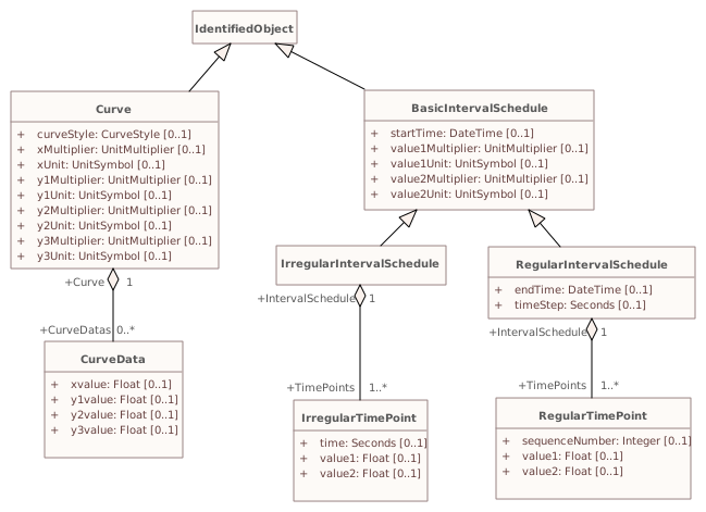
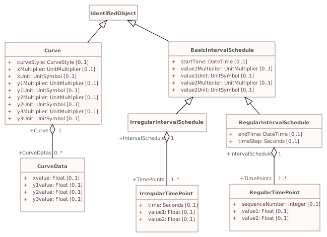
▶▦CurveSchedulei
CHANGED{7DCA2E11-355A-47f2-9EF8-BEAEBD619E5D}
Diagram notes
This diagram shows the common model for curves and time dependent schedules.Diagram metadata — changes
| Baseline | Destination | |
|---|---|---|
| no changes | ||
Diagram notes
This diagram shows the common model for curves and time dependent schedules.▦Diagram
changed
Baseline
Destination
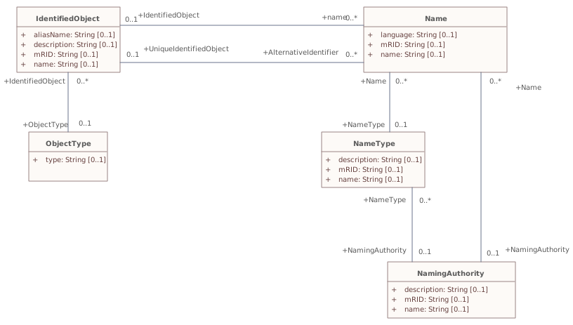
▶▦Namesi
CHANGED{E0451A91-94B6-4771-AA2F-2F1E5235FDE5}
Diagram notes
This diagram shows classes used to assign names to identified objects.Diagram metadata — changes
| Baseline | Destination | |
|---|---|---|
| ModifiedDate | 2021-08-09 10:40:32 | 2021-10-08 16:00:17 |
Diagram notes
This diagram shows classes used to assign names to identified objects.▤Metadata
| Baseline | Destination | |
|---|---|---|
| ModifiedDate | 2021-08-09 10:40:32 | 2021-10-08 16:00:17 |
▦Diagram
changed
Baseline
Destination
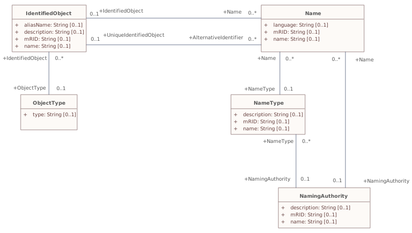
Connectors 3 rerouted · 2 labels movedhover a connector to outline the elements it joins
reroutedName – NamingAuthority
reroutedNameType – Name
reroutedNameType – NamingAuthority
labels movedName – IdentifiedObject
labels movedObjectType – IdentifiedObject
▶▦OperatingSharei
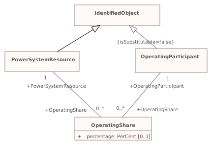
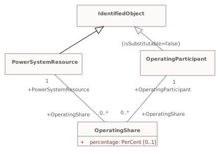
CHANGED{88289F74-ECDD-42e8-A693-6744785B1A0C}
Diagram notes
This diagram shows the common model for operating share.Diagram metadata — changes
| Baseline | Destination | |
|---|---|---|
| no changes | ||
Diagram notes
This diagram shows the common model for operating share.▦Diagram
changed
Baseline
Destination
▶▦Reportingi
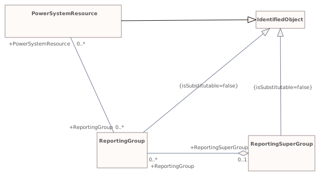
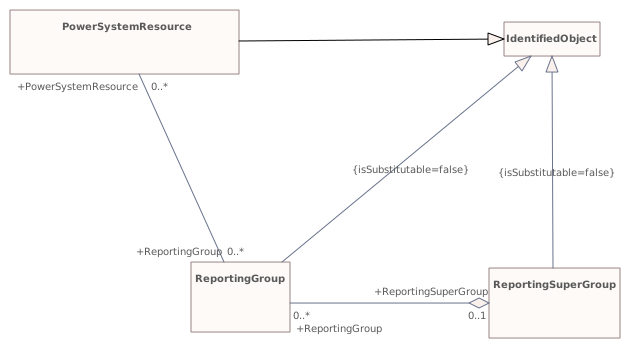
CHANGED{25B521B8-89DF-4043-A8D0-B37B0F772597}
Diagram notes
This diagram shows the common model for ad-hoc reporting.Diagram metadata — changes
| Baseline | Destination | |
|---|---|---|
| no changes | ||
Diagram notes
This diagram shows the common model for ad-hoc reporting.▦Diagram
changed
Baseline
Destination
▶Wiresi
{6C99E9CA-2035-4035-B77F-9217E17D86F4}
Package notes
An extension to the Core and Topology package that models information on the electrical characteristics of Transmission and Distribution networks. This package is used by network applications such as State Estimation, Load Flow and Optimal Power Flow.Package metadata — changes
| Baseline | Destination | |
|---|---|---|
| no changes | ||
Tagged values — changes
| Baseline | Destination | |
|---|---|---|
| no changes | ||
Package notes
An extension to the Core and Topology package that models information on the electrical characteristics of Transmission and Distribution networks. This package is used by network applications such as State Estimation, Load Flow and Optimal Power Flow.Changed classes (5)
▶⚙ACLineSegmenti
CHANGED{625BD764-3907-4d65-8497-7FD09708BD8E}
Class notes
A wire or combination of wires, with consistent electrical characteristics, building a single electrical system, used to carry alternating current between points in the power system.
For symmetrical, transposed three phase lines, it is sufficient to use attributes of the line segment, which describe impedances and admittances for the entire length of the segment. Additionally impedances can be computed by using length and associated per length impedances.
The BaseVoltage at the two ends of ACLineSegments in a Line shall have the same BaseVoltage.nominalVoltage. However, boundary lines may have slightly different BaseVoltage.nominalVoltages and variation is allowed. Larger voltage difference in general requires use of an equivalent branch.Class metadata — changes
| Baseline | Destination | |
|---|---|---|
| no changes | ||
Tagged values — changes
| Baseline | Destination | |
|---|---|---|
| no changes | ||
Class notes
A wire or combination of wires, with consistent electrical characteristics, building a single electrical system, used to carry alternating current between points in the power system.
For symmetrical, transposed three phase lines, it is sufficient to use attributes of the line segment, which describe impedances and admittances for the entire length of the segment. Additionally impedances can be computed by using length and associated per length impedances.
The BaseVoltage at the two ends of ACLineSegments in a Line shall have the same BaseVoltage.nominalVoltage. However, boundary lines may have slightly different BaseVoltage.nominalVoltages and variation is allowed. Larger voltage difference in general requires use of an equivalent branch.⇄Links
CHANGEDAssociation{F29D4402-D392-434d-9E98-8C35F21BD856}
→
Source end — ACLineSegment
| Baseline | Destination | |
|---|---|---|
| RoleNote | (empty) | The AC line segment defined by the wire spacing information |
Target end — WireSpacingInfo
| Baseline | Destination | |
|---|---|---|
| RoleNote | (empty) | The wire spacing information that applies to this AC line segment |
▶⚙ACLineSegmentPhasei
CHANGED{84627F88-F666-4f07-890A-62622070CD0F}
Class notes
Represents a single wire of an alternating current line segment.Class metadata — changes
| Baseline | Destination | |
|---|---|---|
| no changes | ||
Tagged values — changes
| Baseline | Destination | |
|---|---|---|
| no changes | ||
Class notes
Represents a single wire of an alternating current line segment.⇄Links
CHANGEDAssociation{B5F55F86-9C19-4914-99C2-1ACBA0197A2E}
→
Source end — ACLineSegmentPhase
| Baseline | Destination | |
|---|---|---|
| RoleNote | (empty) | AC line segment phase information associated with this wire information. |
Target end — WireInfo
| Baseline | Destination | |
|---|---|---|
| RoleNote | (empty) | Wire information contributing to this AC line segment phase information. |
▶⚙Clampi
CHANGED{7B0758AF-6E8E-438e-BD69-A838A56F256D}
Class notes
A Clamp is a galvanic connection at a line segment where other equipment is connected. A Clamp does not cut the line segment.
A Clamp is ConductingEquipment and has one Terminal with an associated ConnectivityNode. Any other ConductingEquipment can be connected to the Clamp ConnectivityNode.Class metadata — changes
| Baseline | Destination | |
|---|---|---|
| no changes | ||
Tagged values — changes
| Baseline | Destination | |
|---|---|---|
| no changes | ||
Class notes
A Clamp is a galvanic connection at a line segment where other equipment is connected. A Clamp does not cut the line segment.
A Clamp is ConductingEquipment and has one Terminal with an associated ConnectivityNode. Any other ConductingEquipment can be connected to the Clamp ConnectivityNode.⇄Links
CHANGEDAssociation{74BBE709-CFEF-40a9-A120-33F704608576}
→
Source end — Clamp
| Baseline | Destination | |
|---|---|---|
| RoleNote | (empty) | Clamp on which this action is taken. |
Target end — JumperAction
| Baseline | Destination | |
|---|---|---|
| RoleNote | (empty) | Action taken with this jumper. |
CHANGEDAssociation{74C6F744-E53A-4fd0-BBA8-3531659CCC10}
→
Source end — Clamp
| Baseline | Destination | |
|---|---|---|
| RoleNote | (empty) | The clamp that the clamp action is performed on |
Target end — ClampAction
| Baseline | Destination | |
|---|---|---|
| RoleNote | (empty) | The clamp action that is performed on the clamp |
▶⚙EnergyConsumeri
CHANGED{BCEC7EE8-7294-4b50-8216-0286C31A035C}
Class notes
Generic user of energy - a point of consumption on the power system model.
EnergyConsumer.pfixed, .qfixed, .pfixedPct and .qfixedPct have meaning only if there is no LoadResponseCharacteristic associated with EnergyConsumer or if LoadResponseCharacteristic.exponentModel is set to False.Class metadata — changes
| Baseline | Destination | |
|---|---|---|
| no changes | ||
Tagged values — changes
| Baseline | Destination | |
|---|---|---|
| no changes | ||
Class notes
Generic user of energy - a point of consumption on the power system model.
EnergyConsumer.pfixed, .qfixed, .pfixedPct and .qfixedPct have meaning only if there is no LoadResponseCharacteristic associated with EnergyConsumer or if LoadResponseCharacteristic.exponentModel is set to False.⇄Links
CHANGEDAssociation{FED8229A-5B6E-4728-A961-4E85004FEA54}
BaselineEnergyConsumer role EnergyConsumer [0..1] → EnergyConsumerAction role EnergyConsumerAction [0..1]
→
DestinationEnergyConsumer role EnergyConsumer [0..1] → EnergyConsumerAction role EnergyConsumerAction [0..1]
Source end — EnergyConsumer
| Baseline | Destination | |
|---|---|---|
| RoleNote | (empty) | The energy consumer that the energy consumer action is performed on |
Target end — EnergyConsumerAction
| Baseline | Destination | |
|---|---|---|
| RoleNote | (empty) | The energy consumer action that is performed on the energy consumer |
▶⚙ShuntCompensatori
CHANGED{92B30569-5ED0-4fc0-B796-984D9BF75453}
Class notes
A shunt capacitor or reactor or switchable bank of shunt capacitors or reactors. A section of a shunt compensator is an individual capacitor or reactor. A negative value for bPerSection indicates that the compensator is a reactor. ShuntCompensator is a single terminal device. Ground is implied.Class metadata — changes
| Baseline | Destination | |
|---|---|---|
| no changes | ||
Tagged values — changes
| Baseline | Destination | |
|---|---|---|
| no changes | ||
Class notes
A shunt capacitor or reactor or switchable bank of shunt capacitors or reactors. A section of a shunt compensator is an individual capacitor or reactor. A negative value for bPerSection indicates that the compensator is a reactor. ShuntCompensator is a single terminal device. Ground is implied.⇄Links
CHANGEDAssociation{9AE30218-76B9-40f7-A698-BEA89FA25113}
BaselineShuntCompensator role ShuntCompensator [0..1] → ShuntCompensatorAction role ShuntCompensatorAction [0..1]
→
DestinationShuntCompensator role ShuntCompensator [0..1] → ShuntCompensatorAction role ShuntCompensatorAction [0..1]
Source end — ShuntCompensator
| Baseline | Destination | |
|---|---|---|
| RoleNote | (empty) | The shunt compensator that the shunt compensator action is performed on |
Target end — ShuntCompensatorAction
| Baseline | Destination | |
|---|---|---|
| RoleNote | (empty) | The shunt compensator action that is performed on the shunt compensator |
Changed diagrams (5)
▶▦InheritanceHierarchyi
CHANGED{D2B8C355-D454-4084-9966-12E8D7FF6875}
Diagram notes
This diagram describes inheritance between classes in and related to the Wires package.Diagram metadata — changes
| Baseline | Destination | |
|---|---|---|
| no changes | ||
Diagram notes
This diagram describes inheritance between classes in and related to the Wires package.▦Diagram
changed
Baseline
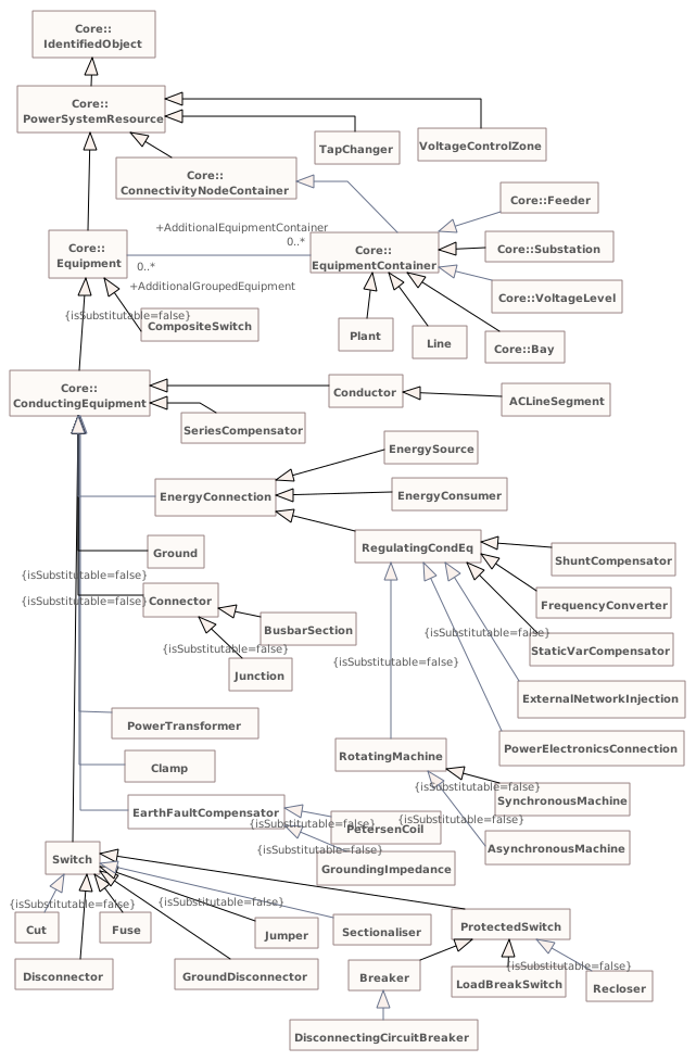
Destination
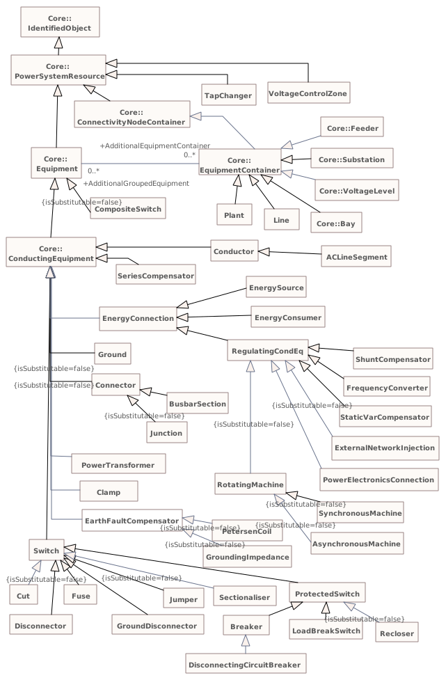
▶▦MutualCouplingi
CHANGED{7CE6A094-D43D-4851-8A1F-D1B06FA7B538}
Diagram notes
Shows mutual coupling models.Diagram metadata — changes
| Baseline | Destination | |
|---|---|---|
| no changes | ||
Diagram notes
Shows mutual coupling models.▦Diagram
changed
Baseline
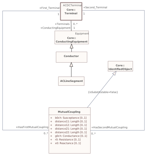
Destination
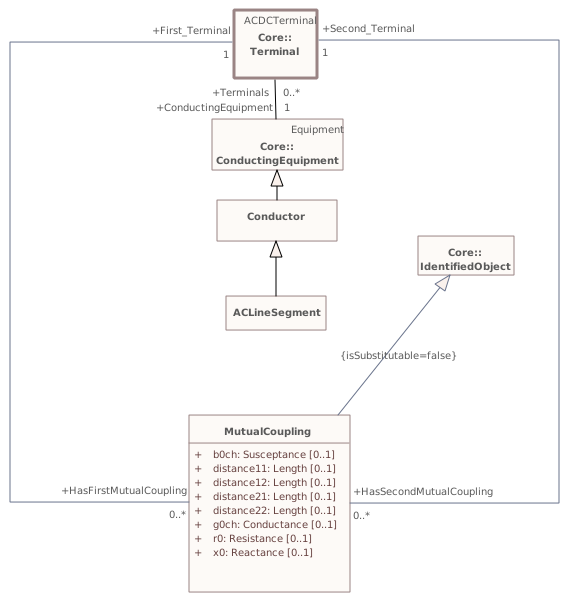
▶▦NamingHierarchyPart1i
CHANGED{422FB39E-1D47-45c4-8623-BADEED124BF6}
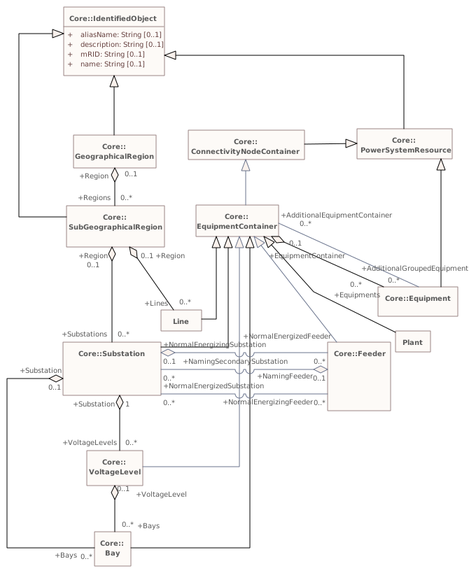
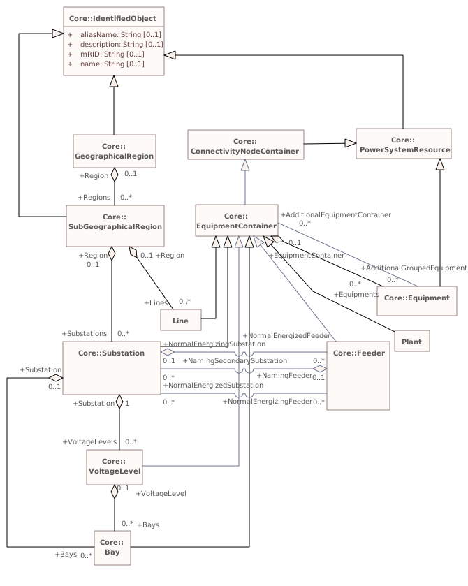
Diagram notes
The diagram shows the upper part of the naming hierarchy. The hierarchy is a way to organize and name equipment. Hence it is tightly related to the IdentifiedObject and it's attributes. The Equipment class is further specialized into many subtypes that are all contained by subclasses of the EquipmentContainer.Diagram metadata — changes
| Baseline | Destination | |
|---|---|---|
| no changes | ||
Diagram notes
The diagram shows the upper part of the naming hierarchy. The hierarchy is a way to organize and name equipment. Hence it is tightly related to the IdentifiedObject and it's attributes. The Equipment class is further specialized into many subtypes that are all contained by subclasses of the EquipmentContainer.▦Diagram
changed
Baseline
Destination
▶▦NamingHierarchyPart2i
CHANGED{3A72A435-5BA5-4809-A5DC-560573D58582}
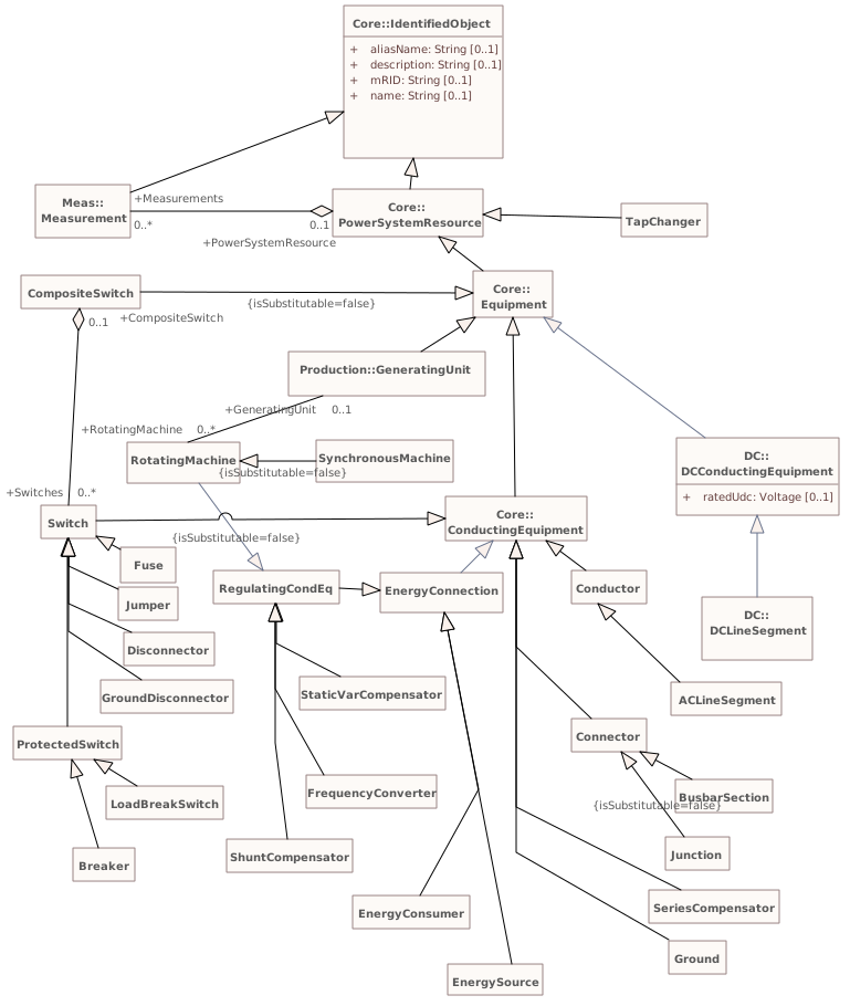
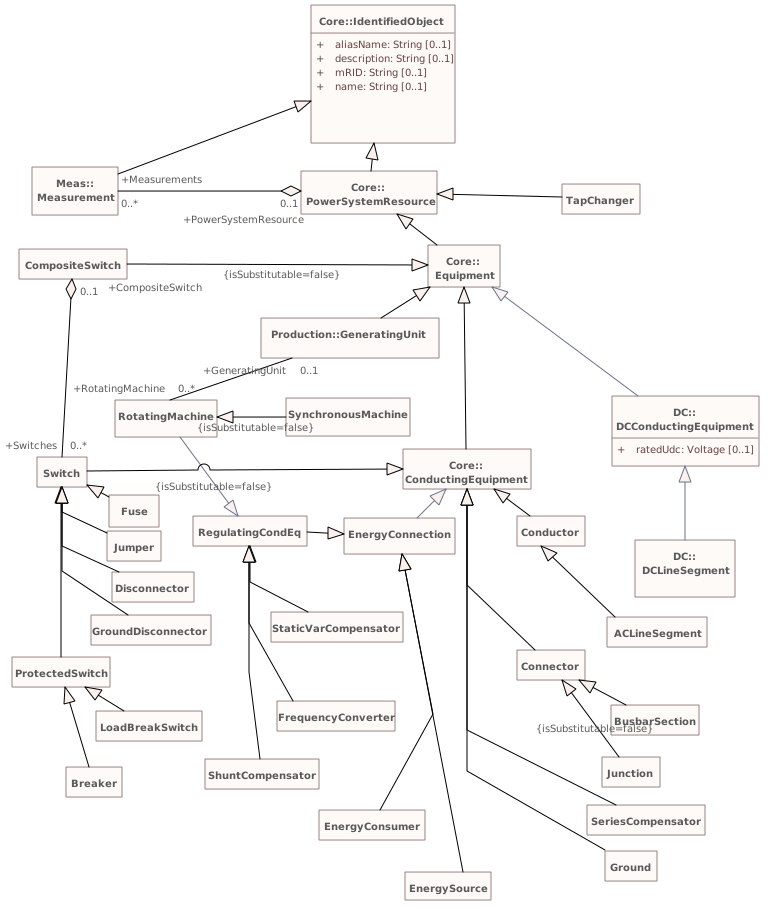
Diagram notes
The diagram shows the lower part of the naming hierarchy. It shows how the Equipment class is further specialized into many subtypes that are all contained by subclasses of the EquipmentContainer. For the subclasses of equipment container refer to part 1 of the diagram.Diagram metadata — changes
| Baseline | Destination | |
|---|---|---|
| no changes | ||
Diagram notes
The diagram shows the lower part of the naming hierarchy. It shows how the Equipment class is further specialized into many subtypes that are all contained by subclasses of the EquipmentContainer. For the subclasses of equipment container refer to part 1 of the diagram.▦Diagram
changed
Baseline
Destination
▶▦Schedulesi
CHANGED{18FA35BC-A253-4a57-A387-6D36B189A250}
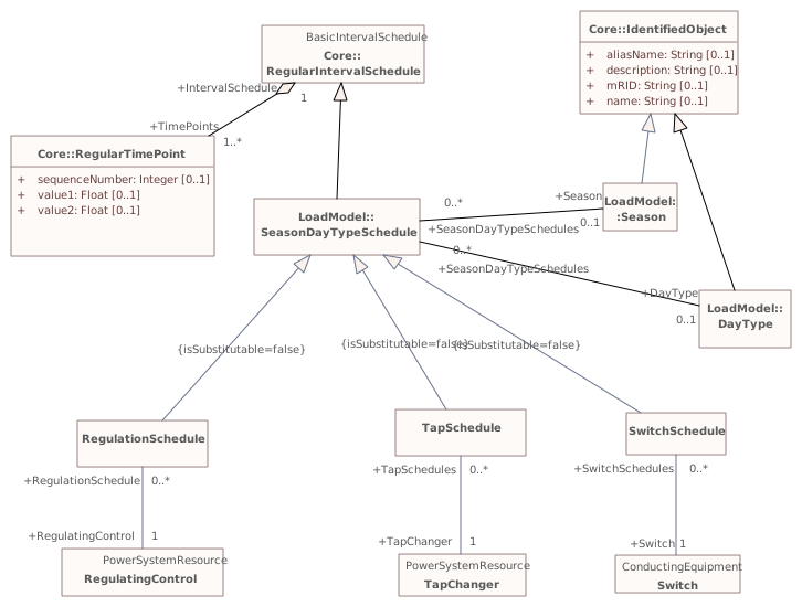
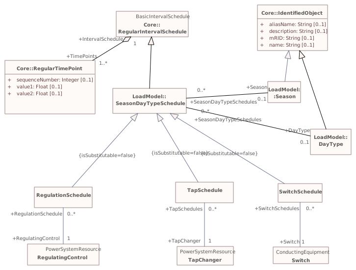
Diagram notes
Shows schedules of wires model.Diagram metadata — changes
| Baseline | Destination | |
|---|---|---|
| no changes | ||
Diagram notes
Shows schedules of wires model.▦Diagram
changed
Baseline
Destination
▶LoadModeli
{427D9D64-CDA2-4070-AAC6-04A32F290872}
Package notes
This package is responsible for modelling the energy consumers and the system load as curves and associated curve data. Special circumstances that may affect the load, such as seasons and day types, are also included here.
This information is used by Load Forecasting and Load Management.Package metadata — changes
| Baseline | Destination | |
|---|---|---|
| no changes | ||
Tagged values — changes
| Baseline | Destination | |
|---|---|---|
| no changes | ||
Package notes
This package is responsible for modelling the energy consumers and the system load as curves and associated curve data. Special circumstances that may affect the load, such as seasons and day types, are also included here.
This information is used by Load Forecasting and Load Management.Package 'LoadModel' has no changes to the 16 classes it contains.
Changed diagrams (1)
▶▦Maini
CHANGED{E25D676B-3E4F-482f-B0D7-4B7A0ADFFFEB}
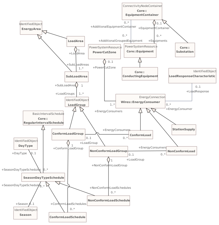
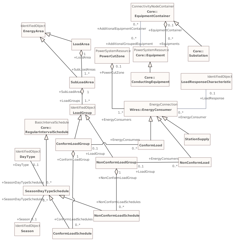
Diagram notes
This diagram shows all classes included in the LoadModel package as well as the key external classes that have associations with LoadModel classes.Diagram metadata — changes
| Baseline | Destination | |
|---|---|---|
| no changes | ||
Diagram notes
This diagram shows all classes included in the LoadModel package as well as the key external classes that have associations with LoadModel classes.▦Diagram
changed
Baseline
Destination
▶Generationi
{6B50A1FD-22E9-4abc-B0B7-F46BBD8B33AE}
Package notes
This package contains packages that have information for Unit Commitment and Economic Dispatch of hydro and thermal generating units, Load Forecasting, Automatic Generation Control, and unit modeling for Training Simulation.Package metadata — changes
| Baseline | Destination | |
|---|---|---|
| no changes | ||
Tagged values — changes
| Baseline | Destination | |
|---|---|---|
| no changes | ||
Package notes
This package contains packages that have information for Unit Commitment and Economic Dispatch of hydro and thermal generating units, Load Forecasting, Automatic Generation Control, and unit modeling for Training Simulation.▶Productioni
{39719C4D-64F6-4704-8202-8CAEF5179709}
Package notes
The production package is responsible for classes which describe various kinds of generators. These classes also provide production costing information which is used to economically allocate demand among committed units and calculate reserve quantities.Package metadata — changes
| Baseline | Destination | |
|---|---|---|
| no changes | ||
Tagged values — changes
| Baseline | Destination | |
|---|---|---|
| no changes | ||
Package notes
The production package is responsible for classes which describe various kinds of generators. These classes also provide production costing information which is used to economically allocate demand among committed units and calculate reserve quantities.Package 'Production' has no changes to the 49 classes it contains.
Changed diagrams (3)
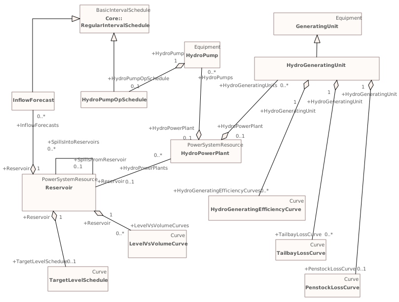
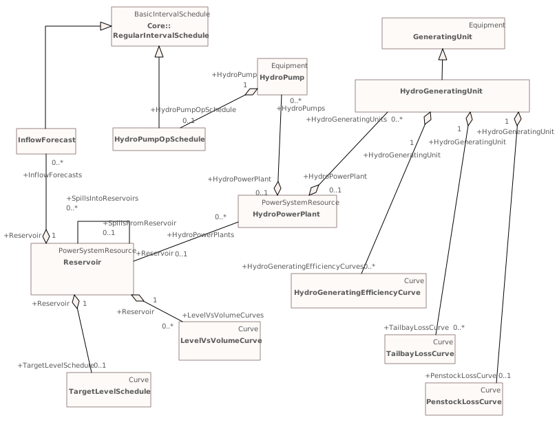
▶▦Hydroi
CHANGED{DE303E99-315E-416c-906A-2195D7E5C62A}
Diagram notes
This diagram shows all classes included in the Hydro package as well as the key external classes that have associations with Hydro classes.Diagram metadata — changes
| Baseline | Destination | |
|---|---|---|
| no changes | ||
Diagram notes
This diagram shows all classes included in the Hydro package as well as the key external classes that have associations with Hydro classes.▦Diagram
changed
Baseline
Destination
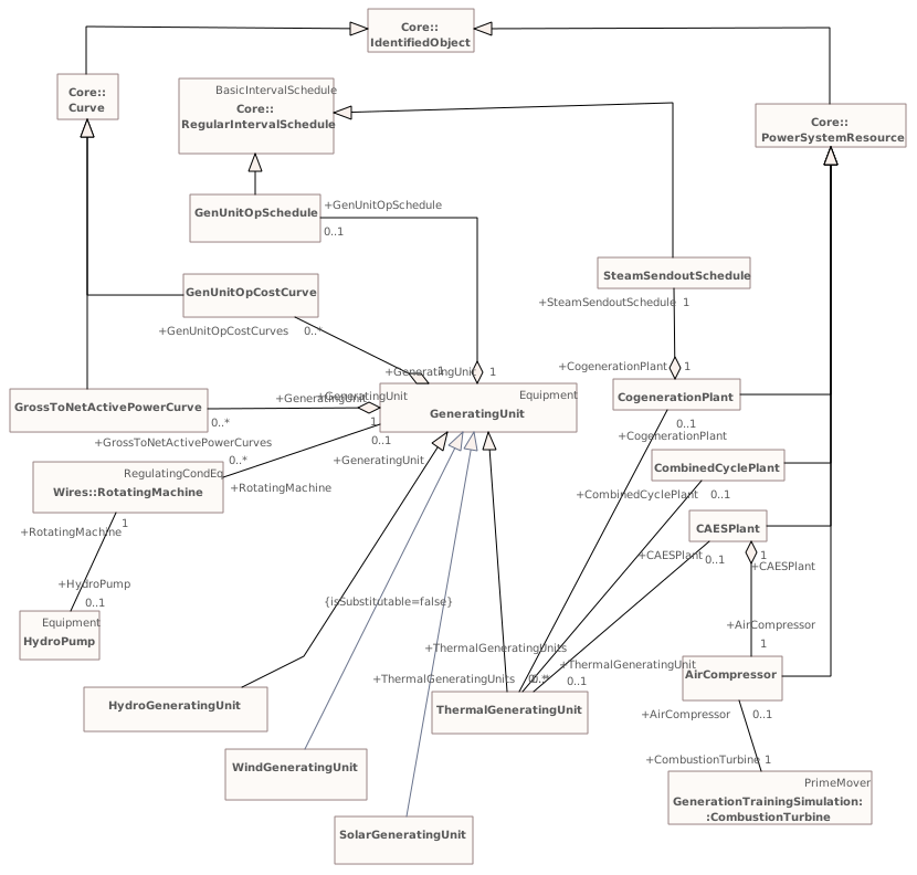
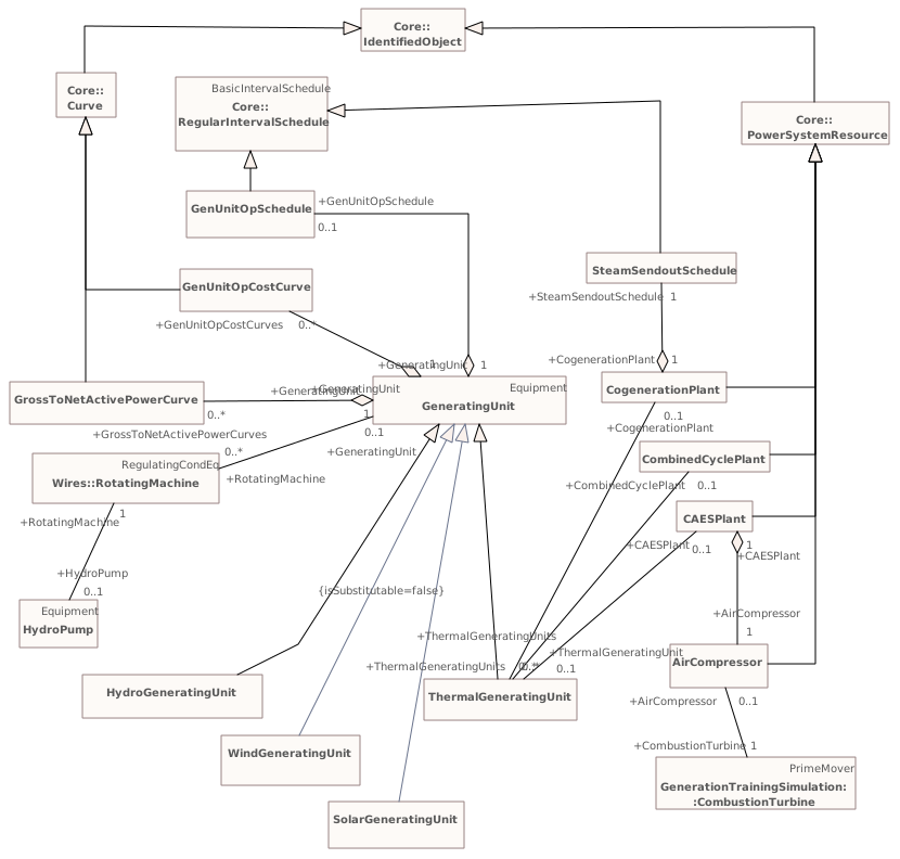
▶▦Maini
CHANGED{F9C40197-0210-4574-A263-DF81545A755B}
Diagram notes
This diagram shows all classes included in the Production package that are needed by both Hydro and Thermal generation. It also shows key external classes that have associations with Production classes.Diagram metadata — changes
| Baseline | Destination | |
|---|---|---|
| no changes | ||
Diagram notes
This diagram shows all classes included in the Production package that are needed by both Hydro and Thermal generation. It also shows key external classes that have associations with Production classes.▦Diagram
changed
Baseline
Destination
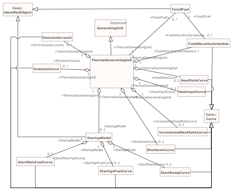
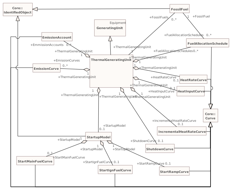
▶▦Thermali
CHANGED{93E625AE-B174-4d96-B127-8B8086E6BE1F}
Diagram notes
This diagram shows all classes included in the Thermal package as well as the key external classes that have associations with Thermal classes.Diagram metadata — changes
| Baseline | Destination | |
|---|---|---|
| no changes | ||
Diagram notes
This diagram shows all classes included in the Thermal package as well as the key external classes that have associations with Thermal classes.▦Diagram
changed
Baseline
Destination
Package 'Generation' has no changes to the 1 diagrams it contains.
▶Equivalentsi
{32F75AB7-7839-4933-BE8C-F162A464FE41}
Package notes
The equivalents package models equivalent networks.Package metadata — changes
| Baseline | Destination | |
|---|---|---|
| no changes | ||
Tagged values — changes
| Baseline | Destination | |
|---|---|---|
| no changes | ||
Package notes
The equivalents package models equivalent networks.Package 'Equivalents' has no changes to the 5 classes it contains.
Changed diagrams (1)
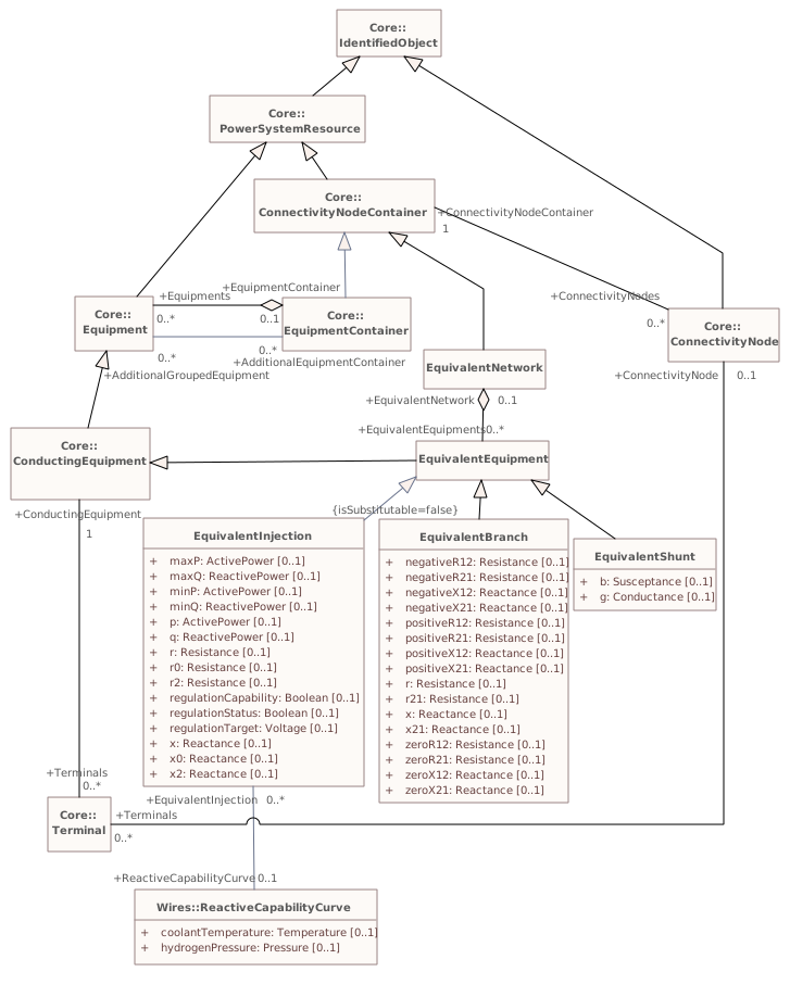
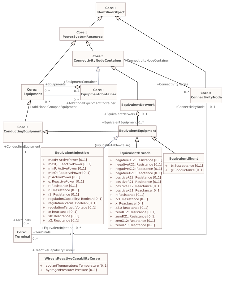
▶▦Maini
CHANGED{15613B15-ECE0-47f2-B5D5-CBA4AA111746}
Diagram notes
Shows model for equivalent networks.Diagram metadata — changes
| Baseline | Destination | |
|---|---|---|
| no changes | ||
Diagram notes
Shows model for equivalent networks.▦Diagram
changed
Baseline
Destination
▶Measi
{6B58A5C3-5CC1-4320-A9D3-2CABB8F9399E}
Package notes
Contains entities that describe dynamic measurement data exchanged between applications.Package metadata — changes
| Baseline | Destination | |
|---|---|---|
| no changes | ||
Tagged values — changes
| Baseline | Destination | |
|---|---|---|
| no changes | ||
Package notes
Contains entities that describe dynamic measurement data exchanged between applications.Changed classes (3)
▶⚙Controli
CHANGED{4EEEE27D-42CD-4efc-8F74-3655BF703F4E}
Class notes
Control is used for supervisory/device control. It represents control outputs that are used to change the state in a process, e.g. close or open breaker, a set point value or a raise lower command.Class metadata — changes
| Baseline | Destination | |
|---|---|---|
| no changes | ||
Tagged values — changes
| Baseline | Destination | |
|---|---|---|
| no changes | ||
Class notes
Control is used for supervisory/device control. It represents control outputs that are used to change the state in a process, e.g. close or open breaker, a set point value or a raise lower command.⇄Links
CHANGEDAssociation{55F3693A-6960-486a-AEB0-EEBB67B10D9A}
→
Source end — ControlAction
| Baseline | Destination | |
|---|---|---|
| RoleNote | (empty) | The control action that is performed on the control |
Target end — Control
| Baseline | Destination | |
|---|---|---|
| RoleNote | (empty) | The control that the control action is performed on. |
▶⚙Measurementi
CHANGED{AB1758FA-3A4D-478f-BE4F-ADC8E2F886CC}
Class notes
A Measurement represents any measured, calculated or non-measured non-calculated quantity. Any piece of equipment may contain Measurements, e.g. a substation may have temperature measurements and door open indications, a transformer may have oil temperature and tank pressure measurements, a bay may contain a number of power flow measurements and a Breaker may contain a switch status measurement.
The PSR - Measurement association is intended to capture this use of Measurement and is included in the naming hierarchy based on EquipmentContainer. The naming hierarchy typically has Measurements as leaves, e.g. Substation-VoltageLevel-Bay-Switch-Measurement.
Some Measurements represent quantities related to a particular sensor location in the network, e.g. a voltage transformer (VT) or potential transformer (PT) at a busbar or a current transformer (CT) at the bar between a breaker and an isolator. The sensing position is not captured in the PSR - Measurement association. Instead it is captured by the Measurement - Terminal association that is used to define the sensing location in the network topology. The location is defined by the connection of the Terminal to ConductingEquipment.
If both a Terminal and PSR are associated, and the PSR is of type ConductingEquipment, the associated Terminal should belong to that ConductingEquipment instance.
When the sensor location is needed both Measurement-PSR and Measurement-Terminal are used. The Measurement-Terminal association is never used alone.Class metadata — changes
| Baseline | Destination | |
|---|---|---|
| no changes | ||
Tagged values — changes
| Baseline | Destination | |
|---|---|---|
| no changes | ||
Class notes
A Measurement represents any measured, calculated or non-measured non-calculated quantity. Any piece of equipment may contain Measurements, e.g. a substation may have temperature measurements and door open indications, a transformer may have oil temperature and tank pressure measurements, a bay may contain a number of power flow measurements and a Breaker may contain a switch status measurement.
The PSR - Measurement association is intended to capture this use of Measurement and is included in the naming hierarchy based on EquipmentContainer. The naming hierarchy typically has Measurements as leaves, e.g. Substation-VoltageLevel-Bay-Switch-Measurement.
Some Measurements represent quantities related to a particular sensor location in the network, e.g. a voltage transformer (VT) or potential transformer (PT) at a busbar or a current transformer (CT) at the bar between a breaker and an isolator. The sensing position is not captured in the PSR - Measurement association. Instead it is captured by the Measurement - Terminal association that is used to define the sensing location in the network topology. The location is defined by the connection of the Terminal to ConductingEquipment.
If both a Terminal and PSR are associated, and the PSR is of type ConductingEquipment, the associated Terminal should belong to that ConductingEquipment instance.
When the sensor location is needed both Measurement-PSR and Measurement-Terminal are used. The Measurement-Terminal association is never used alone.⇄Links
CHANGEDAssociation{016DD996-A1EA-4bb6-8349-AF38EEDFF7AD}
→
Source end — Asset
| Baseline | Destination | |
|---|---|---|
| RoleNote | (empty) | Asset that has a measurement |
Target end
no changes
CHANGEDAssociation{0566ECD1-879E-43fc-AFB0-A8B79BFC4DEE}
→
Source end — MeasurementAction
| Baseline | Destination | |
|---|---|---|
| RoleNote | (empty) | The measurement action that is performed on the measurement |
Target end — Measurement
| Baseline | Destination | |
|---|---|---|
| RoleNote | (empty) | The measurement that the measurement action is performed on |
CHANGEDAssociation{F582AAC6-446D-49be-9380-09E21CAA0CCF}
→
Source end — Locations
| Baseline | Destination | |
|---|---|---|
| RoleNote | (empty) | Location of this measurement. |
Target end — Measurements
| Baseline | Destination | |
|---|---|---|
| RoleNote | (empty) | All measurements at this location. |
▶⚙MeasurementValuei
CHANGED{E6D7B57A-456A-43b5-838B-3CFB466EE4C4}
Class notes
The current state for a measurement. A state value is an instance of a measurement from a specific source. Measurements can be associated with many state values, each representing a different source for the measurement.Class metadata — changes
| Baseline | Destination | |
|---|---|---|
| no changes | ||
Tagged values — changes
| Baseline | Destination | |
|---|---|---|
| no changes | ||
Class notes
The current state for a measurement. A state value is an instance of a measurement from a specific source. Measurements can be associated with many state values, each representing a different source for the measurement.⇄Links
CHANGEDAssociation{A0C93754-F2B4-4597-96C0-BDCA60E5BC09}
BaselineProcedureDataSet role ProcedureDataSet [0..*] → MeasurementValue role MeasurementValue [0..*]
→
DestinationProcedureDataSet role ProcedureDataSet [0..*] → MeasurementValue role MeasurementValue [0..*]
Source end — ProcedureDataSet
| Baseline | Destination | |
|---|---|---|
| RoleNote | (empty) | Procedure data set that applies to this mesurement value. |
Target end — MeasurementValue
| Baseline | Destination | |
|---|---|---|
| RoleNote | (empty) | Measurement value related to this procedure data set. |
Changed diagrams (1)
▶▦MeasurementInheritancei
CHANGED{5DF6F48B-1076-4edf-9F46-0132E1D9A930}
Diagram notes
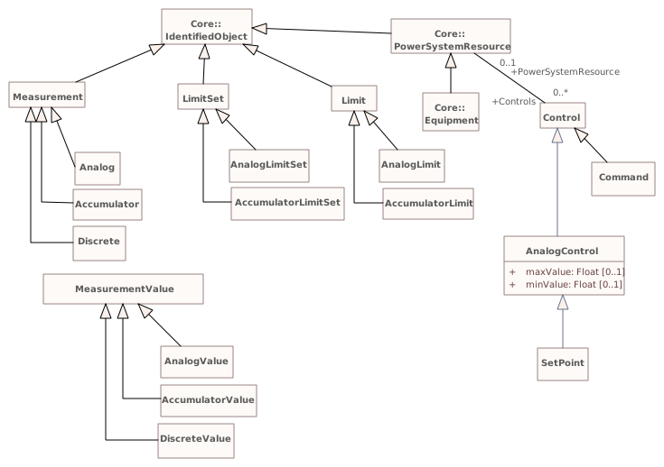
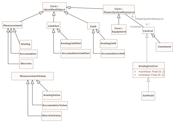
This diagram shows the measurement classes inheritance.Diagram metadata — changes
| Baseline | Destination | |
|---|---|---|
| no changes | ||
Diagram notes
This diagram shows the measurement classes inheritance.▦Diagram
changed
Baseline
Destination
▶DiagramLayouti
{BD6471E7-9929-4251-A731-BB65A6ABD2BF}
Package notes
This package describes diagram layout. This describes how objects are arranged in a coordinate system rather than how they are rendered.Package metadata — changes
| Baseline | Destination | |
|---|---|---|
| no changes | ||
Tagged values — changes
| Baseline | Destination | |
|---|---|---|
| no changes | ||
Package notes
This package describes diagram layout. This describes how objects are arranged in a coordinate system rather than how they are rendered.Package 'DiagramLayout' has no changes to the 9 classes it contains.
Changed diagrams (1)
▶▦DiagramLayouti
CHANGED{99E05246-80CF-4712-8EDF-605446BBFADE}
Diagram notes
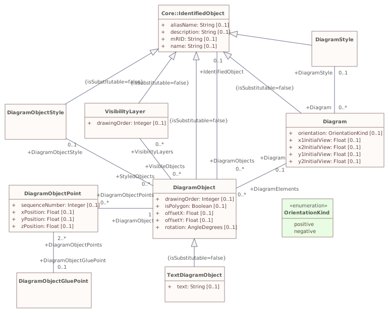
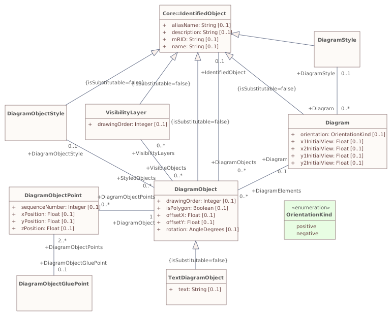
Shows model for diagram layout.Diagram metadata — changes
| Baseline | Destination | |
|---|---|---|
| no changes | ||
Diagram notes
Shows model for diagram layout.▦Diagram
changed
Baseline
Destination
▶OperationalLimitsi
{CCAAF4EA-4C50-4438-86F9-63852950B3CA}
Package notes
This package models a specification of limits associated with equipment and other operational entities.Package metadata — changes
| Baseline | Destination | |
|---|---|---|
| no changes | ||
Tagged values — changes
| Baseline | Destination | |
|---|---|---|
| no changes | ||
Package notes
This package models a specification of limits associated with equipment and other operational entities.Package 'OperationalLimits' has no changes to the 10 classes it contains.
Changed diagrams (1)
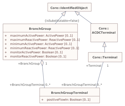
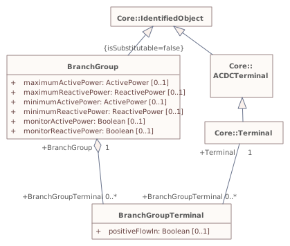
▶▦BranchGroupi
CHANGED{DE2F00E8-B731-43ce-B01C-7267ED3D9F4E}
Diagram notes
This diagram shows the model for monitoring combined flows on groups of branches.Diagram metadata — changes
| Baseline | Destination | |
|---|---|---|
| no changes | ||
Diagram notes
This diagram shows the model for monitoring combined flows on groups of branches.▦Diagram
changed
Baseline
Destination
▶ControlAreai
{3A4198A2-F8DC-4ff1-B669-3064688AF4DD}
Package notes
The ControlArea package models area specifications which can be used for a variety of purposes. The package as a whole models potentially overlapping control area specifications for the purpose of actual generation control, load forecast area load capture, or powerflow based analysis.Package metadata — changes
| Baseline | Destination | |
|---|---|---|
| no changes | ||
Tagged values — changes
| Baseline | Destination | |
|---|---|---|
| no changes | ||
Package notes
The ControlArea package models area specifications which can be used for a variety of purposes. The package as a whole models potentially overlapping control area specifications for the purpose of actual generation control, load forecast area load capture, or powerflow based analysis.Package 'ControlArea' has no changes to the 6 classes it contains.
Changed diagrams (1)
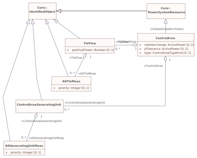
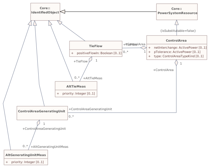
▶▦ControlAreaInheritancei
CHANGED{AA2D75EA-1B1C-41b5-8C61-999912681F91}
Diagram notes
Shows the inheritance of classes in this package.Diagram metadata — changes
| Baseline | Destination | |
|---|---|---|
| no changes | ||
Diagram notes
Shows the inheritance of classes in this package.▦Diagram
changed
Baseline
Destination
▶Contingencyi
{5AFF4730-5CFE-48e6-961A-077143DE2082}
Package notes
Contingencies to be studied.Package metadata — changes
| Baseline | Destination | |
|---|---|---|
| no changes | ||
Tagged values — changes
| Baseline | Destination | |
|---|---|---|
| no changes | ||
Package notes
Contingencies to be studied.Package 'Contingency' has no changes to the 4 classes it contains.
Changed diagrams (1)
▶▦Contingencyi
CHANGED{F06848B5-DB6D-4a40-91C8-00E7BC6F1823}
Diagram notes
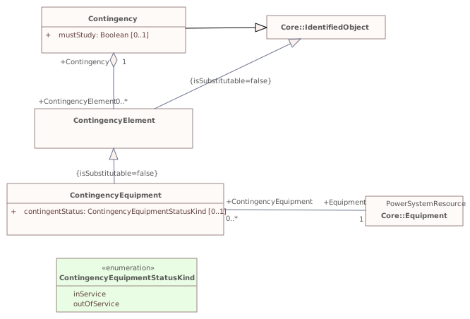
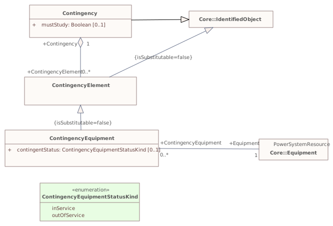
This diagram shows contingency model inheritance and associations.Diagram metadata — changes
| Baseline | Destination | |
|---|---|---|
| no changes | ||
Diagram notes
This diagram shows contingency model inheritance and associations.▦Diagram
changed
Baseline
Destination
▶Protectioni
{3F02E213-ECF8-4f14-9AD5-D4A252FE300A}
Package notes
An extension to the Core and Wires packages that models information for protection equipment such as relays. These entities are used within training simulators and distribution network fault location applications.Package metadata — changes
| Baseline | Destination | |
|---|---|---|
| no changes | ||
Tagged values — changes
| Baseline | Destination | |
|---|---|---|
| no changes | ||
Package notes
An extension to the Core and Wires packages that models information for protection equipment such as relays. These entities are used within training simulators and distribution network fault location applications.Package 'Protection' has no changes to the 4 classes it contains.
Changed diagrams (1)
▶▦Maini
CHANGED{9AF2AFF5-A5C5-487d-BE22-9DADEDA9929E}
Diagram notes
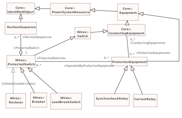
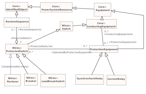
This diagram shows all classes included in the Protection package as well as the key external classes that have associations with Protection classes.Diagram metadata — changes
| Baseline | Destination | |
|---|---|---|
| no changes | ||
Diagram notes
This diagram shows all classes included in the Protection package as well as the key external classes that have associations with Protection classes.▦Diagram
changed
Baseline
Destination
▶Faultsi
{59BC9A2E-B8E4-4c5f-B1D8-2C6502296346}
Package notes
The package describes faults that may happen to conducting equipment, e.g. tree falling on a power line.Package metadata — changes
| Baseline | Destination | |
|---|---|---|
| no changes | ||
Tagged values — changes
| Baseline | Destination | |
|---|---|---|
| no changes | ||
Package notes
The package describes faults that may happen to conducting equipment, e.g. tree falling on a power line.Changed classes (2)
▶⚙Faulti
CHANGED{73ABECF2-4B28-4c55-8665-0882A2C8BCA4}
Class notes
Abnormal condition causing current flow through conducting equipment, such as caused by equipment failure or short circuits from objects not typically modelled (for example, a tree falling on a line).Class metadata — changes
| Baseline | Destination | |
|---|---|---|
| no changes | ||
Tagged values — changes
| Baseline | Destination | |
|---|---|---|
| no changes | ||
Class notes
Abnormal condition causing current flow through conducting equipment, such as caused by equipment failure or short circuits from objects not typically modelled (for example, a tree falling on a line).⇄Links
CHANGEDAssociation{7F84E357-68DD-4257-BD11-EE226FADA1E6}
→
Source end — Fault
| Baseline | Destination | |
|---|---|---|
| RoleNote | (empty) | All faults at this location. |
Target end — Location
| Baseline | Destination | |
|---|---|---|
| RoleNote | (empty) | Location of this fault. |
▶⚙FaultCauseTypei
CHANGED{FA0CB393-8E7C-411c-B4F1-14073D940EED}
Class notes
Type of cause of the fault.Class metadata — changes
| Baseline | Destination | |
|---|---|---|
| no changes | ||
Tagged values — changes
| Baseline | Destination | |
|---|---|---|
| no changes | ||
Class notes
Type of cause of the fault.⇄Links
CHANGEDAssociation{B79138C2-DB7B-43a8-A72B-77D615EB381B}
→
DestinationConfigurationEvent role ConfigurationEvent [0..*] → FaultCauseType role FaultCauseType [1]
Link metadata
| Baseline | Destination | |
|---|---|---|
| Stereotype | Part 3 Ext | (empty) |
Source end — ConfigurationEvent
| Baseline | Destination | |
|---|---|---|
| RoleNote | (empty) | All configuration events created for this fault cause type. |
| Stereotype | Part 3 Ext | (empty) |
Target end — FaultCauseType
| Baseline | Destination | |
|---|---|---|
| RoleNote | (empty) | Fault cause type whose change resulted in this configuration event. |
| Stereotype | Part 3 Ext | (empty) |
Package 'Faults' has no changes to the 1 diagrams it contains.
▶SCADAi
{C397A471-682D-4757-89C3-C65DCE1842A7}
Package notes
Contains entities to model information used by Supervisory Control and Data Acquisition (SCADA) applications. Supervisory control supports operator control of equipment, such as opening or closing a breaker. Data acquisition gathers telemetered data from various sources. The subtypes of the Telemetry entity deliberately match the UCA and IEC 61850 definitions.
This package also supports alarm presentation but it is not expected to be used by other applications.Package metadata — changes
| Baseline | Destination | |
|---|---|---|
| no changes | ||
Tagged values — changes
| Baseline | Destination | |
|---|---|---|
| no changes | ||
Package notes
Contains entities to model information used by Supervisory Control and Data Acquisition (SCADA) applications. Supervisory control supports operator control of equipment, such as opening or closing a breaker. Data acquisition gathers telemetered data from various sources. The subtypes of the Telemetry entity deliberately match the UCA and IEC 61850 definitions.
This package also supports alarm presentation but it is not expected to be used by other applications.Package 'SCADA' has no changes to the 7 classes it contains.
Changed diagrams (1)
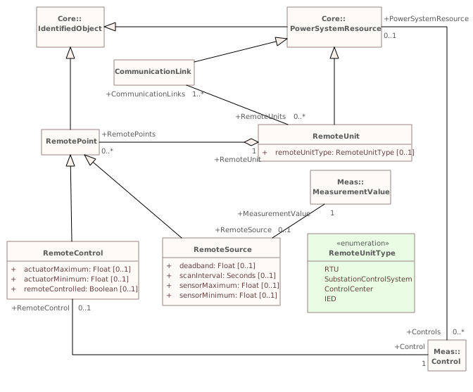
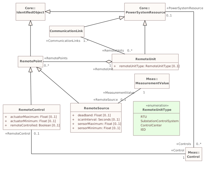
▶▦Maini
CHANGED{DCCD95DF-1D4D-4a31-ADC9-82410B121566}
Diagram notes
This diagram shows all classes included in the SCADA package as well as the key external classes that have associations with SCADA classes.Diagram metadata — changes
| Baseline | Destination | |
|---|---|---|
| no changes | ||
Diagram notes
This diagram shows all classes included in the SCADA package as well as the key external classes that have associations with SCADA classes.▦Diagram
changed
Baseline
Destination
▶Part303i
MOVEDfrom
Package notes
Part of the canonical CIM published as IEC 61970-303.Package metadata — changes
| Baseline | Destination | |
|---|---|---|
| ParentPackage | InfIEC61970 | IEC61970 |
Tagged values — changes
| Baseline | Destination | |
|---|---|---|
| no changes | ||
InfIEC61970{097BFA4A-EAE9-4618-B4D1-896C3B3BB77D}Package notes
Part of the canonical CIM published as IEC 61970-303.▶GenericDataSeti
{8FF85768-B48A-4be5-9113-0DD28B347634}
Package notes
Contains classes used for generic dataset modelling.Package metadata — changes
| Baseline | Destination | |
|---|---|---|
| no changes | ||
Tagged values — changes
| Baseline | Destination | |
|---|---|---|
| no changes | ||
Package notes
Contains classes used for generic dataset modelling.Changed classes (4)
▶⚙ChangeSeti
CHANGED{EDB0ACC9-0CE3-439f-ADC6-2D753A220486}
Class notes
Describes a set of changes that can be applied in different situations. A given registered target object MRID may only be referenced once by the contained change set members.Class metadata — changes
| Baseline | Destination | |
|---|---|---|
| no changes | ||
Tagged values — changes
| Baseline | Destination | |
|---|---|---|
| no changes | ||
Class notes
Describes a set of changes that can be applied in different situations. A given registered target object MRID may only be referenced once by the contained change set members.⇄Links
CHANGEDAssociation{D718248A-D448-492a-AE40-8C6ED4992EB3}
→
Source end
no changes
Target end — ChangeSet
| Baseline | Destination | |
|---|---|---|
| Role | Changeset | Change |
▶⚙ChangeSetMemberi
CHANGED{B579C575-1165-4e6c-AFEF-991BBA193E2B}
Class notes
A CRUD-style data object.Class metadata — changes
| Baseline | Destination | |
|---|---|---|
| no changes | ||
Tagged values — changes
| Baseline | Destination | |
|---|---|---|
| no changes | ||
Class notes
A CRUD-style data object.⇄Links
CHANGEDAssociation{D718248A-D448-492a-AE40-8C6ED4992EB3}
→
Source end
no changes
Target end — ChangeSet
| Baseline | Destination | |
|---|---|---|
| Role | Changeset | Change |
▶⚙DataSeti
CHANGED{28D05F59-6B53-4c1f-A18D-EE6B9CC533F9}
Class notes
A generic container of a version of instance data. The MRID can be used in an audit trail, not in reusable script intended to work with new versions of data.
A dataset could be serialized multiple times and in multiple technologies, yet retain the same identity.Class metadata — changes
| Baseline | Destination | |
|---|---|---|
| no changes | ||
Tagged values — changes
| Baseline | Destination | |
|---|---|---|
| no changes | ||
Class notes
A generic container of a version of instance data. The MRID can be used in an audit trail, not in reusable script intended to work with new versions of data.
A dataset could be serialized multiple times and in multiple technologies, yet retain the same identity.≡Attributes
| Attribute | Baseline | Destination | Notes (destination, redlined) | |||||||||||||||||||||||||||||||||||||||||||||
|---|---|---|---|---|---|---|---|---|---|---|---|---|---|---|---|---|---|---|---|---|---|---|---|---|---|---|---|---|---|---|---|---|---|---|---|---|---|---|---|---|---|---|---|---|---|---|---|---|
| descriptioni{14F272FF-25AE-4d6a-9BFE-FF46458C9848}show details | String [0..1] | removed from model | ||||||||||||||||||||||||||||||||||||||||||||||
Attribute notes (baseline) The description is a free human readable text describing or naming the object. It may be non unique and may not correlate to a naming hierarchy.Attribute metadata — changes
Tagged values — changes
| ||||||||||||||||||||||||||||||||||||||||||||||||
| namei{4DFBBA72-867F-4d84-8F39-69AFECF9990E}show details | String [0..1] | removed from model | ||||||||||||||||||||||||||||||||||||||||||||||
Attribute notes (baseline) The name is any free human readable and possibly non unique text naming the object.Attribute metadata — changes
Tagged values — changes
| ||||||||||||||||||||||||||||||||||||||||||||||||
⇄Links
DELETEDAssociation{A554D44F-37A9-44b7-878F-CDC356BA0B3A}
Link metadata
| Baseline | Destination | |
|---|---|---|
| Direction | Unspecified | |
| IsLeaf | false | |
| IsRoot | false | |
| Type | Association |
Source end
| Baseline | Destination | |
|---|---|---|
| Cardinality | 0..* | |
| Containment | Unspecified | |
| End | Data | |
| IsAggregation | none | |
| IsChangeable | none | |
| IsNavigable | true | |
| Ordering | false | |
| Role | Data | |
| RoleNote | The data sets that make use of the profile. | |
| Scope | public | |
| TargetScope | instance |
Target end
| Baseline | Destination | |
|---|---|---|
| Cardinality | 1..* | |
| Containment | Unspecified | |
| End | Profile | |
| IsAggregation | none | |
| IsChangeable | none | |
| IsNavigable | true | |
| Ordering | false | |
| Role | Profile | |
| RoleNote | The profiles that describe the contents of the data set and the rules governing the contents of the data set. | |
| Scope | public | |
| TargetScope | instance |
▶⚙Profilei
CHANGED{BC499E60-2398-46aa-A340-8421A864B0C1}
Class notes
Describes the existence of a profile. The MRID is usually defined as a static value by the document or artifact that defines the contents of the profile and the rules for using the profile.Class metadata — changes
| Baseline | Destination | |
|---|---|---|
| no changes | ||
Tagged values — changes
| Baseline | Destination | |
|---|---|---|
| no changes | ||
Class notes
Describes the existence of a profile. The MRID is usually defined as a static value by the document or artifact that defines the contents of the profile and the rules for using the profile.⇄Links
DELETEDAssociation{A554D44F-37A9-44b7-878F-CDC356BA0B3A}
Link metadata
| Baseline | Destination | |
|---|---|---|
| Direction | Unspecified | |
| IsLeaf | false | |
| IsRoot | false | |
| Type | Association |
Source end
| Baseline | Destination | |
|---|---|---|
| Cardinality | 0..* | |
| Containment | Unspecified | |
| End | Data | |
| IsAggregation | none | |
| IsChangeable | none | |
| IsNavigable | true | |
| Ordering | false | |
| Role | Data | |
| RoleNote | The data sets that make use of the profile. | |
| Scope | public | |
| TargetScope | instance |
Target end
| Baseline | Destination | |
|---|---|---|
| Cardinality | 1..* | |
| Containment | Unspecified | |
| End | Profile | |
| IsAggregation | none | |
| IsChangeable | none | |
| IsNavigable | true | |
| Ordering | false | |
| Role | Profile | |
| RoleNote | The profiles that describe the contents of the data set and the rules governing the contents of the data set. | |
| Scope | public | |
| TargetScope | instance |
Changed diagrams (1)
▶▦GenericDataSeti
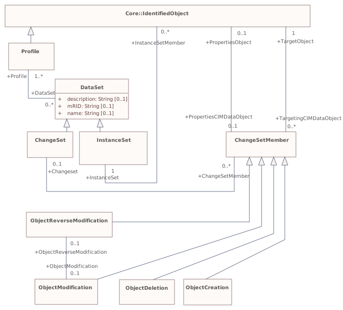
CHANGED{A5A07B09-93CB-423d-8595-8653C21E725B}
Diagram notes
Shows the generic dataset core classes.Diagram metadata — changes
| Baseline | Destination | |
|---|---|---|
| ModifiedDate | 2019-03-08 20:18:20 | 2021-09-29 10:41:05 |
Diagram notes
Shows the generic dataset core classes.▤Metadata
| Baseline | Destination | |
|---|---|---|
| ModifiedDate | 2019-03-08 20:18:20 | 2021-09-29 10:41:05 |
▦Diagram
removedchanged
Baseline
Destination
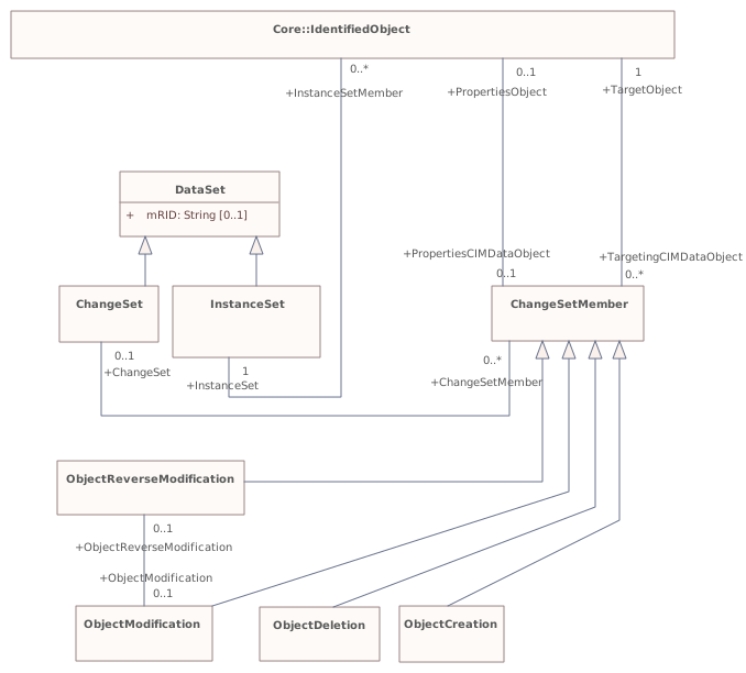
Connectors 2 removed · 2 rerouted · 1 labels moved · 1 labels changedhover a connector to outline the elements it joins
removedDataSet – Profile
removedProfile – IdentifiedObject
reroutedChangeSet – DataSet
reroutedInstanceSet – DataSet
labels movedChangeSetMember – IdentifiedObject
labels changedChangeSetMember – ChangeSetrole name Changeset → ChangeSet
▶Dynamicsi
{A71B9185-6D48-40f4-B618-485C08C4F269}
Package notes
The CIM dynamic model definitions reflect the most common IEEE or, in the case of wind models, IEC, representations of models as well as models included in some of the transient stability software widely used by utilities.
These dynamic models are intended to ensure interoperability between different vendors’ software products currently in use by electric utility energy companies, utilities, Transmission System Operators (TSOs), Regional Transmission Organizations (RTOs), and Independent System Operators (ISOs). It is important to note that each vendor is free to select its own internal implementation of these models. Differences in vendor results, as long as they are within accepted engineering practice, caused by different internal representations, are acceptable.
Unless explicitly stated otherwise, the following modelling conventions are followed:
- limited integrators are of the non-windup type;
- it shall be possible to enter a time constant of zero (where it makes sense).Package metadata — changes
| Baseline | Destination | |
|---|---|---|
| no changes | ||
Tagged values — changes
| Baseline | Destination | |
|---|---|---|
| no changes | ||
Package notes
The CIM dynamic model definitions reflect the most common IEEE or, in the case of wind models, IEC, representations of models as well as models included in some of the transient stability software widely used by utilities.
These dynamic models are intended to ensure interoperability between different vendors’ software products currently in use by electric utility energy companies, utilities, Transmission System Operators (TSOs), Regional Transmission Organizations (RTOs), and Independent System Operators (ISOs). It is important to note that each vendor is free to select its own internal implementation of these models. Differences in vendor results, as long as they are within accepted engineering practice, caused by different internal representations, are acceptable.
Unless explicitly stated otherwise, the following modelling conventions are followed:
- limited integrators are of the non-windup type;
- it shall be possible to enter a time constant of zero (where it makes sense).▶StandardModelsi
{1BEB429C-BFD0-49c6-9556-AC7BA58C2202}
Package notes
This subclause contains standard dynamic model specifications grouped into packages by standard function block (type of equipment being modelled).
In the CIM, standard dynamic models are expressed by means of a class named with the standard model name and attributes reflecting each of the parameters necessary to describe the behaviour of an instance of the standard model.Package metadata — changes
| Baseline | Destination | |
|---|---|---|
| no changes | ||
Tagged values — changes
| Baseline | Destination | |
|---|---|---|
| no changes | ||
Package notes
This subclause contains standard dynamic model specifications grouped into packages by standard function block (type of equipment being modelled).
In the CIM, standard dynamic models are expressed by means of a class named with the standard model name and attributes reflecting each of the parameters necessary to describe the behaviour of an instance of the standard model.▶SynchronousMachineDynamicsi
{448F8675-D39C-4fe0-9450-2791AE603EFC}
Package notes
For conventional power generating units (e.g., thermal, hydro, combustion turbine), a synchronous machine model represents the electrical characteristics of the generator and the mechanical characteristics of the turbine-generator rotational inertia. Large industrial motors or groups of similar motors can be represented by individual motor models which are represented as generators with negative active power in the static (power flow) data.
The interconnection with the electrical network equations can differ among simulation tools. The tool only needs to know the synchronous machine to establish the correct interconnection. The interconnection with the motor’s equipment could also differ due to input and output signals required by standard models.Package metadata — changes
| Baseline | Destination | |
|---|---|---|
| no changes | ||
Tagged values — changes
| Baseline | Destination | |
|---|---|---|
| no changes | ||
Package notes
For conventional power generating units (e.g., thermal, hydro, combustion turbine), a synchronous machine model represents the electrical characteristics of the generator and the mechanical characteristics of the turbine-generator rotational inertia. Large industrial motors or groups of similar motors can be represented by individual motor models which are represented as generators with negative active power in the static (power flow) data.
The interconnection with the electrical network equations can differ among simulation tools. The tool only needs to know the synchronous machine to establish the correct interconnection. The interconnection with the motor’s equipment could also differ due to input and output signals required by standard models.Package 'SynchronousMachineDynamics' has no changes to the 8 classes it contains.
Changed diagrams (1)
▶▦SynchronousMachineDynamicsi
CHANGED{54E9C659-8B6C-4948-A2ED-1F2B84C0A17C}
Diagram notes
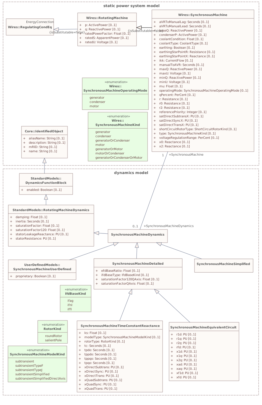
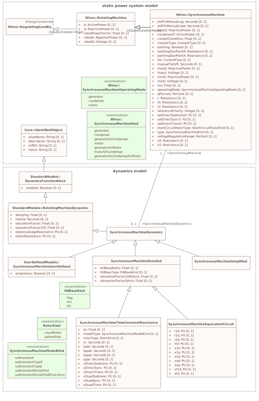
This diagram shows static power system model classes and dynamics model classes related to the synchronous machine dynamics model. An association between the SynchronousMachineDynamics class and the SynchronousMachine class provides a means for relating the dynamics model to the static model.Diagram metadata — changes
| Baseline | Destination | |
|---|---|---|
| no changes | ||
Diagram notes
This diagram shows static power system model classes and dynamics model classes related to the synchronous machine dynamics model. An association between the SynchronousMachineDynamics class and the SynchronousMachine class provides a means for relating the dynamics model to the static model.▦Diagram
changed
Baseline
Destination
▶AsynchronousMachineDynamicsi
{5D284657-A8B5-4b22-A1BE-60220021422B}
Package notes
An asynchronous machine model represents a (induction) generator or motor with no external connection to the rotor windings, e.g. a squirrel-cage induction machine.
The interconnection with the electrical network equations can differ among simulation tools. The program only needs to know the terminal to which this asynchronous machine is connected in order to establish the correct interconnection. The interconnection with the motor’s equipment could also differ due to input and output signals required by standard models.
The asynchronous machine model is used to model wind generators type 1 and type 2. For these, normal practice is to include the rotor flux transients and neglect the stator flux transients.Package metadata — changes
| Baseline | Destination | |
|---|---|---|
| no changes | ||
Tagged values — changes
| Baseline | Destination | |
|---|---|---|
| no changes | ||
Package notes
An asynchronous machine model represents a (induction) generator or motor with no external connection to the rotor windings, e.g. a squirrel-cage induction machine.
The interconnection with the electrical network equations can differ among simulation tools. The program only needs to know the terminal to which this asynchronous machine is connected in order to establish the correct interconnection. The interconnection with the motor’s equipment could also differ due to input and output signals required by standard models.
The asynchronous machine model is used to model wind generators type 1 and type 2. For these, normal practice is to include the rotor flux transients and neglect the stator flux transients.Package 'AsynchronousMachineDynamics' has no changes to the 3 classes it contains.
Changed diagrams (1)
▶▦AsynchronousMachineDynamicsi
CHANGED{25AB5834-2B99-4846-9C8F-855D6A80D650}
Diagram notes
This diagram shows static power system model classes and dynamics model classes related to the asynchronous machine dynamics model. An association between the AsynchronousMachineDynamics class and the AsynchronousMachine class provides a means for relating the dynamics model to the static model.Diagram metadata — changes
| Baseline | Destination | |
|---|---|---|
| no changes | ||
Diagram notes
This diagram shows static power system model classes and dynamics model classes related to the asynchronous machine dynamics model. An association between the AsynchronousMachineDynamics class and the AsynchronousMachine class provides a means for relating the dynamics model to the static model.▦Diagram
changed
Baseline
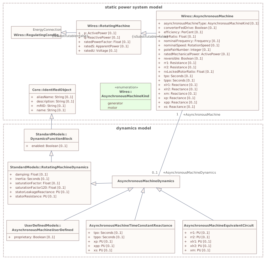
Destination
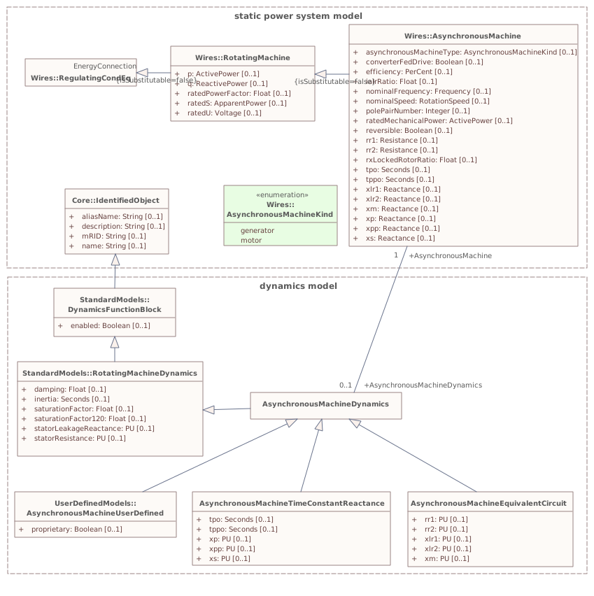
▶TurbineGovernorDynamicsi
{40DA7439-D5DD-4608-85C0-87CF5444B24E}
Package notes
The turbine-governor model is linked to one or two synchronous generators and determines the shaft mechanical power (<i>Pm</i>) or torque (<i>Tm</i>) for the generator model.
Unlike IEEE standard models for other function blocks, the three IEEE turbine-governor standard models (GovHydroIEEE0, GovHydroIEEE2, and GovSteamIEEE1) are documented in IEEE Transactions, not in IEEE standards. For that reason, diagrams are supplied for those models.
A 2012 IEEE report, <i><u>Dynamic Models for Turbine-Governors in Power System Studies</u></i>, provides updated information on a variety of models including IEEE, vendor and reliability authority models. Fully incorporating the results of that report into the CIM dynamics model is a future effort.Package metadata — changes
| Baseline | Destination | |
|---|---|---|
| no changes | ||
Tagged values — changes
| Baseline | Destination | |
|---|---|---|
| no changes | ||
Package notes
The turbine-governor model is linked to one or two synchronous generators and determines the shaft mechanical power (<i>Pm</i>) or torque (<i>Tm</i>) for the generator model.
Unlike IEEE standard models for other function blocks, the three IEEE turbine-governor standard models (GovHydroIEEE0, GovHydroIEEE2, and GovSteamIEEE1) are documented in IEEE Transactions, not in IEEE standards. For that reason, diagrams are supplied for those models.
A 2012 IEEE report, <i><u>Dynamic Models for Turbine-Governors in Power System Studies</u></i>, provides updated information on a variety of models including IEEE, vendor and reliability authority models. Fully incorporating the results of that report into the CIM dynamics model is a future effort.Package 'TurbineGovernorDynamics' has no changes to the 38 classes it contains.
Changed diagrams (1)
▶▦TurbineGovernorDynamicsi
CHANGED{D646BBA5-04C5-4745-9D16-606392088DF9}
Diagram notes
This diagram shows dynamic standard model turbine-governor classes and their inheritance from the TurbineGovernorDynamics class.Diagram metadata — changes
| Baseline | Destination | |
|---|---|---|
| no changes | ||
Diagram notes
This diagram shows dynamic standard model turbine-governor classes and their inheritance from the TurbineGovernorDynamics class.▦Diagram
changed
Baseline
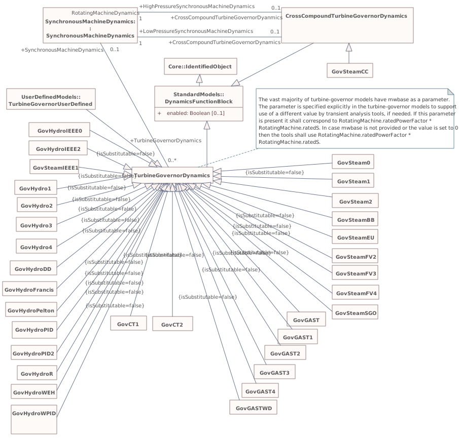
Destination
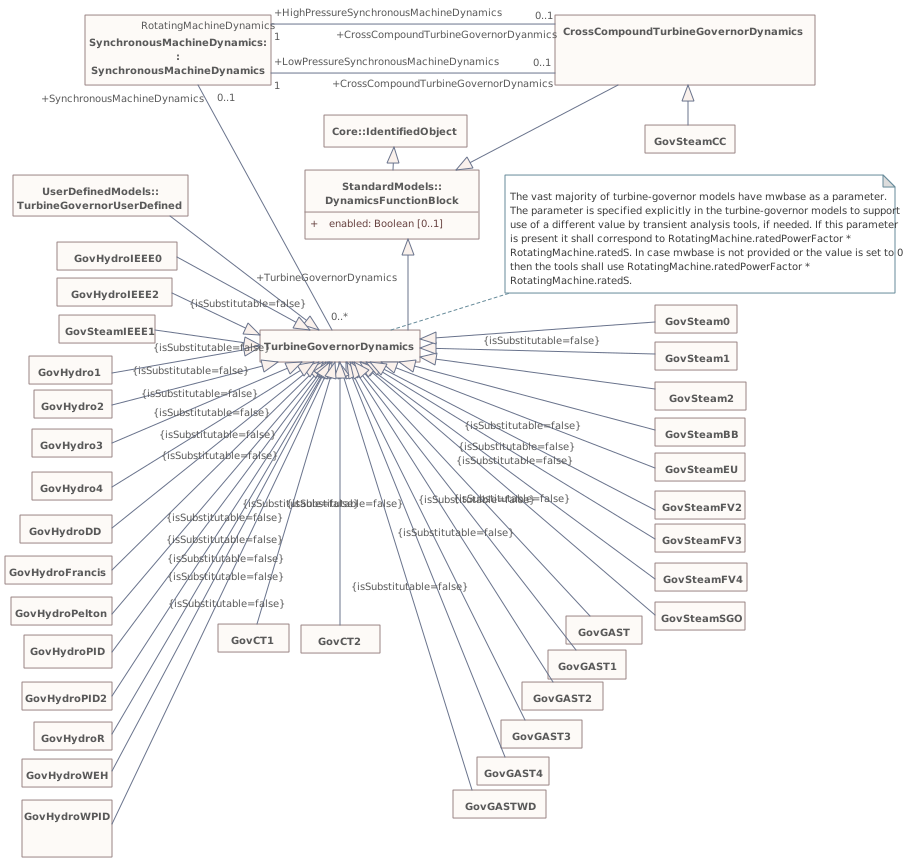
▶TurbineLoadControllerDynamicsi
{F0E43C7F-6E03-4b93-B0AF-2111023CA155}
Package notes
A turbine load controller acts to maintain turbine power at a set value by continuous adjustment of the turbine governor speed-load reference.Package metadata — changes
| Baseline | Destination | |
|---|---|---|
| no changes | ||
Tagged values — changes
| Baseline | Destination | |
|---|---|---|
| no changes | ||
Package notes
A turbine load controller acts to maintain turbine power at a set value by continuous adjustment of the turbine governor speed-load reference.Package 'TurbineLoadControllerDynamics' has no changes to the 2 classes it contains.
Changed diagrams (1)
▶▦TurbineLoadControllerDynamicsi
CHANGED{EA37FCB1-4727-4ecd-94F5-0C25650651A1}
Diagram notes
This diagram shows dynamic standard model turbine load controller classes and their inheritance from the TurbineLoadControllerDynamics class.Diagram metadata — changes
| Baseline | Destination | |
|---|---|---|
| no changes | ||
Diagram notes
This diagram shows dynamic standard model turbine load controller classes and their inheritance from the TurbineLoadControllerDynamics class.▦Diagram
changed
Baseline
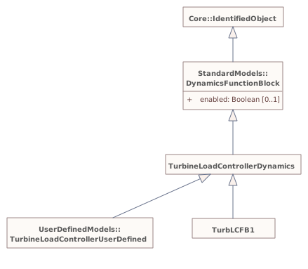
Destination
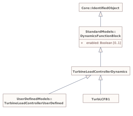
▶MechanicalLoadDynamicsi
{54ED4DD8-2593-43f5-9A32-43679D605D36}
Package notes
A mechanical load represents the variation in a motor's shaft torque or power as a function of shaft speed.Package metadata — changes
| Baseline | Destination | |
|---|---|---|
| no changes | ||
Tagged values — changes
| Baseline | Destination | |
|---|---|---|
| no changes | ||
Package notes
A mechanical load represents the variation in a motor's shaft torque or power as a function of shaft speed.Package 'MechanicalLoadDynamics' has no changes to the 2 classes it contains.
Changed diagrams (1)
▶▦MechanicalLoadDynamicsi
CHANGED{5653B8A5-52C9-401e-811E-69E155E17018}
Diagram notes
This diagram shows dynamic standard model mechanical load classes and their inheritance from the MechanicalLoadDynamics class.Diagram metadata — changes
| Baseline | Destination | |
|---|---|---|
| no changes | ||
Diagram notes
This diagram shows dynamic standard model mechanical load classes and their inheritance from the MechanicalLoadDynamics class.▦Diagram
changed
Baseline
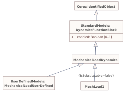
Destination
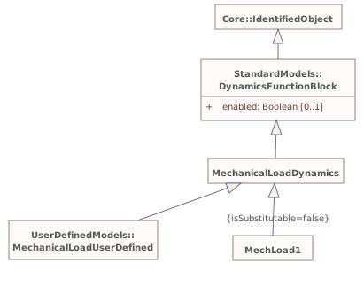
▶ExcitationSystemDynamicsi
{829F67E7-F698-4aa7-95C2-13C616AB6B78}
Package notes
The excitation system model provides the field voltage (<i>Efd</i>) for a synchronous machine model. It is linked to a specific generator (synchronous machine).
The representation of all limits used by the models (not including IEEE standard models) shall comply with the representation defined in the Annex E of the IEEE 421.5-2005, unless specified differently in the documentation of the model.
The parameters are different for each excitation system model; the same parameter name can have different meaning in different models.Package metadata — changes
| Baseline | Destination | |
|---|---|---|
| no changes | ||
Tagged values — changes
| Baseline | Destination | |
|---|---|---|
| no changes | ||
Package notes
The excitation system model provides the field voltage (<i>Efd</i>) for a synchronous machine model. It is linked to a specific generator (synchronous machine).
The representation of all limits used by the models (not including IEEE standard models) shall comply with the representation defined in the Annex E of the IEEE 421.5-2005, unless specified differently in the documentation of the model.
The parameters are different for each excitation system model; the same parameter name can have different meaning in different models.Package 'ExcitationSystemDynamics' has no changes to the 62 classes it contains.
Changed diagrams (1)
▶▦ExcitationSystemDynamicsi
CHANGED{6F433799-BA80-4d4a-ABD1-BD898279F311}
Diagram notes
This diagram shows dynamic standard model excitation system classes and their inheritance from the ExcitationSystemDynamics class.Diagram metadata — changes
| Baseline | Destination | |
|---|---|---|
| no changes | ||
Diagram notes
This diagram shows dynamic standard model excitation system classes and their inheritance from the ExcitationSystemDynamics class.▦Diagram
changed
Baseline
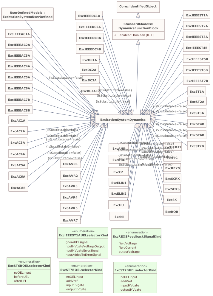
Destination
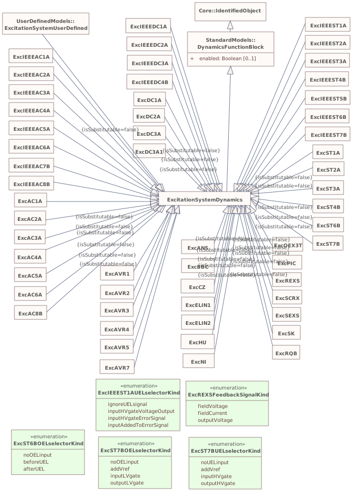
▶OverexcitationLimiterDynamicsi
{CB5C7172-23DD-4cc0-ACF3-557E0496AFCD}
Package notes
Overexcitation limiters (OELs) are also referred to as <i>maximum excitation limiters </i>and <i>field current limiters. </i>The possibility of voltage collapse in stressed power systems increases the importance of modelling these limiters in studies of system conditions that cause machines to operate at high levels of excitation for a sustained period, such as voltage collapse or system-islanding. Such events typically occur over a long time frame compared with transient or small-signal stability simulations.Package metadata — changes
| Baseline | Destination | |
|---|---|---|
| no changes | ||
Tagged values — changes
| Baseline | Destination | |
|---|---|---|
| no changes | ||
Package notes
Overexcitation limiters (OELs) are also referred to as <i>maximum excitation limiters </i>and <i>field current limiters. </i>The possibility of voltage collapse in stressed power systems increases the importance of modelling these limiters in studies of system conditions that cause machines to operate at high levels of excitation for a sustained period, such as voltage collapse or system-islanding. Such events typically occur over a long time frame compared with transient or small-signal stability simulations.Package 'OverexcitationLimiterDynamics' has no changes to the 5 classes it contains.
Changed diagrams (1)
▶▦OverexcitationLimiterDynamicsi
CHANGED{FC47C181-4791-474a-AB30-CF1D0E20F49F}
Diagram notes
This diagram shows dynamic standard model overexcitation limiter classes and their inheritance from the OverexcitationLimiterDynamics class.Diagram metadata — changes
| Baseline | Destination | |
|---|---|---|
| no changes | ||
Diagram notes
This diagram shows dynamic standard model overexcitation limiter classes and their inheritance from the OverexcitationLimiterDynamics class.▦Diagram
changed
Baseline
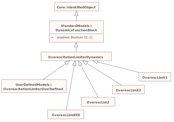
Destination
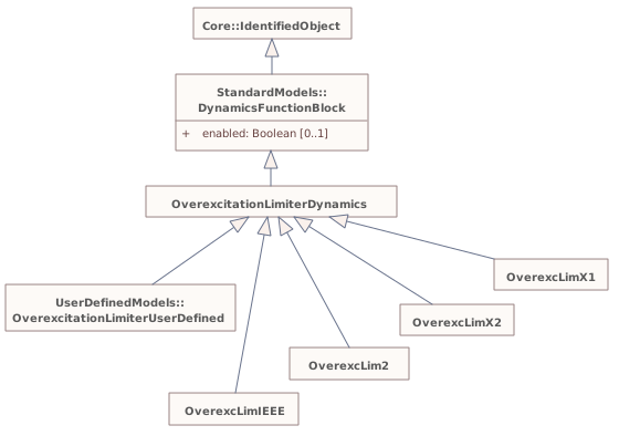
▶UnderexcitationLimiterDynamicsi
{6601D8F5-D2D3-4743-A9D8-51CADC84A53A}
Package notes
Underexcitation limiters (UELs) act to boost excitation. The UEL typically senses either a combination of voltage and current of the synchronous machine or a combination of real and reactive power. Some UELs utilize a temperature or pressure recalibration feature, in which the UEL characteristic is shifted depending upon the generator cooling gas temperature or pressure.Package metadata — changes
| Baseline | Destination | |
|---|---|---|
| no changes | ||
Tagged values — changes
| Baseline | Destination | |
|---|---|---|
| no changes | ||
Package notes
Underexcitation limiters (UELs) act to boost excitation. The UEL typically senses either a combination of voltage and current of the synchronous machine or a combination of real and reactive power. Some UELs utilize a temperature or pressure recalibration feature, in which the UEL characteristic is shifted depending upon the generator cooling gas temperature or pressure.Package 'UnderexcitationLimiterDynamics' has no changes to the 6 classes it contains.
Changed diagrams (1)
▶▦UnderexcitationLimiterDynamicsi
CHANGED{02C1E27A-FA01-4b4b-B496-F6BEDA3C6717}
Diagram notes
This diagram shows dynamic standard model underexcitation limiter classes and their inheritance from the UnderexcitationLimiterDynamics class.Diagram metadata — changes
| Baseline | Destination | |
|---|---|---|
| no changes | ||
Diagram notes
This diagram shows dynamic standard model underexcitation limiter classes and their inheritance from the UnderexcitationLimiterDynamics class.▦Diagram
changed
Baseline
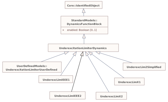
Destination
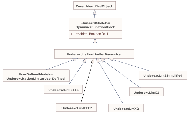
▶PowerSystemStabilizerDynamicsi
{15788FE9-6C55-412c-8AB7-F3F1EB004BDF}
Package notes
The power system stabilizer (PSS) model provides an input (<i>Vs</i>) to the excitation system model to improve damping of system oscillations. A variety of input signals can be used depending on the particular design.Package metadata — changes
| Baseline | Destination | |
|---|---|---|
| no changes | ||
Tagged values — changes
| Baseline | Destination | |
|---|---|---|
| no changes | ||
Package notes
The power system stabilizer (PSS) model provides an input (<i>Vs</i>) to the excitation system model to improve damping of system oscillations. A variety of input signals can be used depending on the particular design.Package 'PowerSystemStabilizerDynamics' has no changes to the 20 classes it contains.
Changed diagrams (1)
▶▦PowerSystemStabilizerDynamicsi
CHANGED{38DA7CE6-AE51-4221-B943-C23D17DBDE6B}
Diagram notes
This diagram shows dynamic standard model power system stabilizer classes and their inheritance from the PowerSystemStabilizerDynamics class.Diagram metadata — changes
| Baseline | Destination | |
|---|---|---|
| no changes | ||
Diagram notes
This diagram shows dynamic standard model power system stabilizer classes and their inheritance from the PowerSystemStabilizerDynamics class.▦Diagram
changed
Baseline
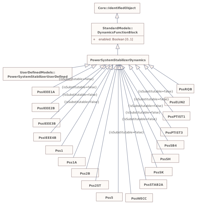
Destination
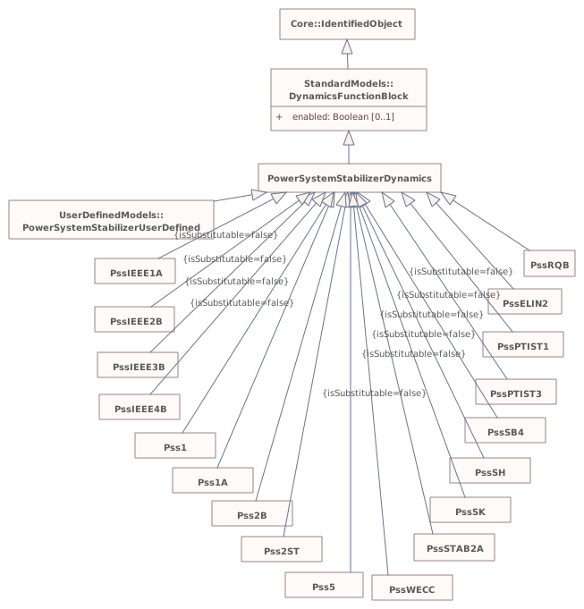
▶DiscontinuousExcitationControlDynamicsi
{510FA576-60DA-4709-96D0-60C754D1875E}
Package notes
In certain system configurations, continuous excitation control with terminal voltage and power system stabilizing regulator input signals does not ensure that the potential of the excitation system for improving system stability is fully exploited. For these situations, discontinuous excitation control signals can be employed to enhance stability following large transient disturbances.
<font color="#0f0f0f">For additional information please refer to IEEE 421.5-2005, 12.</font>Package metadata — changes
| Baseline | Destination | |
|---|---|---|
| no changes | ||
Tagged values — changes
| Baseline | Destination | |
|---|---|---|
| no changes | ||
Package notes
In certain system configurations, continuous excitation control with terminal voltage and power system stabilizing regulator input signals does not ensure that the potential of the excitation system for improving system stability is fully exploited. For these situations, discontinuous excitation control signals can be employed to enhance stability following large transient disturbances.
<font color="#0f0f0f">For additional information please refer to IEEE 421.5-2005, 12.</font>Package 'DiscontinuousExcitationControlDynamics' has no changes to the 4 classes it contains.
Changed diagrams (1)
▶▦DiscontinuousExcitationControlDynamicsi
CHANGED{93B7D510-DFD1-470f-A764-E40D53B3F93A}
Diagram notes
This diagram shows dynamic standard model discontinuous excitation control classes and their inheritance from the DiscontinuousExcitationControlDynamics class.Diagram metadata — changes
| Baseline | Destination | |
|---|---|---|
| no changes | ||
Diagram notes
This diagram shows dynamic standard model discontinuous excitation control classes and their inheritance from the DiscontinuousExcitationControlDynamics class.▦Diagram
changed
Baseline
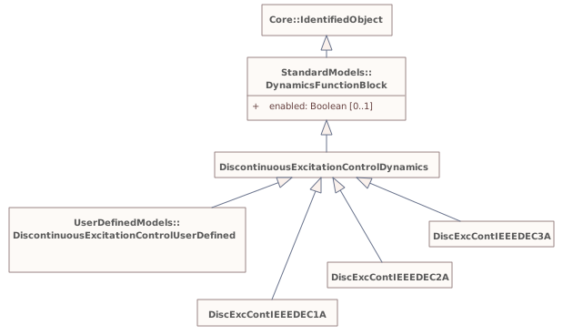
Destination
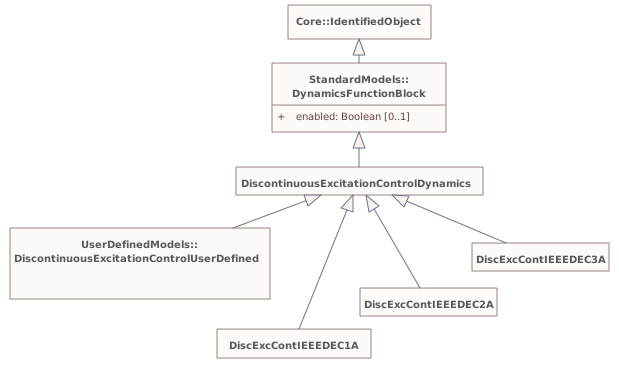
▶PFVArControllerType1Dynamicsi
{DB4B66D7-C753-481b-9C15-D0753561B765}
Package notes
<font color="#0f0f0f">Excitation systems for synchronous machines are sometimes supplied with an optional means of automatically adjusting generator output reactive power (VAr) or power factor (PF) to a user-specified value. This can be accomplished with either a reactive power or power factor controller or regulator. A reactive power or power factor controller is defined as a PF/VAr controller in IEEE 421.1 as “a control function that acts through the reference adjuster to modify the voltage regulator set point to maintain the synchronous machine steady-state power factor or reactive power at a predetermined value.” </font>
<font color="#0f0f0f">For additional information please refer to IEEE 421.5-2005, 11.</font>Package metadata — changes
| Baseline | Destination | |
|---|---|---|
| no changes | ||
Tagged values — changes
| Baseline | Destination | |
|---|---|---|
| no changes | ||
Package notes
<font color="#0f0f0f">Excitation systems for synchronous machines are sometimes supplied with an optional means of automatically adjusting generator output reactive power (VAr) or power factor (PF) to a user-specified value. This can be accomplished with either a reactive power or power factor controller or regulator. A reactive power or power factor controller is defined as a PF/VAr controller in IEEE 421.1 as “a control function that acts through the reference adjuster to modify the voltage regulator set point to maintain the synchronous machine steady-state power factor or reactive power at a predetermined value.” </font>
<font color="#0f0f0f">For additional information please refer to IEEE 421.5-2005, 11.</font>Package 'PFVArControllerType1Dynamics' has no changes to the 3 classes it contains.
Changed diagrams (1)
▶▦PFVArControllerType1Dynamicsi
CHANGED{E5E56E46-8B1A-43d6-88B0-4C85E096AD7B}
Diagram notes
This diagram shows dynamic standard model power factor or VAr controller type 1 classes and their inheritance from the PFVArControllerType1Dynamics class.Diagram metadata — changes
| Baseline | Destination | |
|---|---|---|
| no changes | ||
Diagram notes
This diagram shows dynamic standard model power factor or VAr controller type 1 classes and their inheritance from the PFVArControllerType1Dynamics class.▦Diagram
changed
Baseline
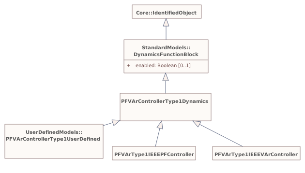
Destination
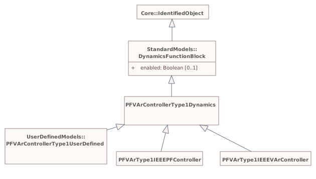
▶VoltageAdjusterDynamicsi
{35B78447-A031-4927-A915-5C69304A72D2}
Package notes
<font color="#0f0f0f">A voltage adjuster is a reference adjuster that uses inputs from a reactive power or power factor controller to modify the voltage regulator set point to maintain the synchronous machine steady-state power factor or reactive power at a predetermined value. </font>
<font color="#0f0f0f">For additional information please refer to IEEE 421.5-2005, 11.</font>Package metadata — changes
| Baseline | Destination | |
|---|---|---|
| no changes | ||
Tagged values — changes
| Baseline | Destination | |
|---|---|---|
| no changes | ||
Package notes
<font color="#0f0f0f">A voltage adjuster is a reference adjuster that uses inputs from a reactive power or power factor controller to modify the voltage regulator set point to maintain the synchronous machine steady-state power factor or reactive power at a predetermined value. </font>
<font color="#0f0f0f">For additional information please refer to IEEE 421.5-2005, 11.</font>Package 'VoltageAdjusterDynamics' has no changes to the 2 classes it contains.
Changed diagrams (1)
▶▦VoltageAdjusterDynamicsi
CHANGED{98EECFEA-7320-4d23-A006-FB39CEBEC0AE}
Diagram notes
This diagram shows dynamic standard model voltage adjuster classes and their inheritance from the VoltageAdjusterDynamics class.Diagram metadata — changes
| Baseline | Destination | |
|---|---|---|
| no changes | ||
Diagram notes
This diagram shows dynamic standard model voltage adjuster classes and their inheritance from the VoltageAdjusterDynamics class.▦Diagram
changed
Baseline
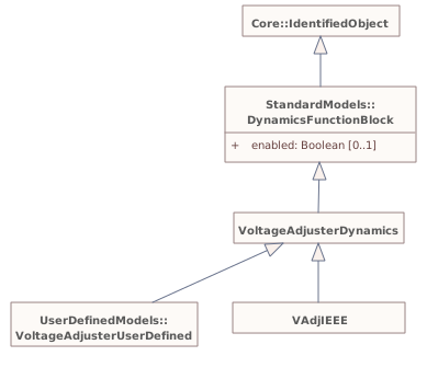
Destination
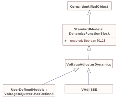
▶PFVArControllerType2Dynamicsi
{9AF74EDB-FFF5-4083-A7D5-48644244A045}
Package notes
<font color="#0f0f0f">A var/pf regulator is defined as “a synchronous machine regulator that functions to maintain the power factor or reactive component of power at a predetermined value.” </font>
<font color="#0f0f0f">For additional information please refer to IEEE 421.5-2005, 11.</font>
<font color="#0f0f0f">
</font>Package metadata — changes
| Baseline | Destination | |
|---|---|---|
| no changes | ||
Tagged values — changes
| Baseline | Destination | |
|---|---|---|
| no changes | ||
Package notes
<font color="#0f0f0f">A var/pf regulator is defined as “a synchronous machine regulator that functions to maintain the power factor or reactive component of power at a predetermined value.” </font>
<font color="#0f0f0f">For additional information please refer to IEEE 421.5-2005, 11.</font>
<font color="#0f0f0f">
</font>Package 'PFVArControllerType2Dynamics' has no changes to the 4 classes it contains.
Changed diagrams (1)
▶▦PFVArControllerType2Dynamicsi
CHANGED{99C16D20-6A74-4483-A25E-34444E865297}
Diagram notes
This diagram shows dynamic standard model power factor or VAr controller type 2 classes and their inheritance from the PFVArControllerType2Dynamics class.Diagram metadata — changes
| Baseline | Destination | |
|---|---|---|
| no changes | ||
Diagram notes
This diagram shows dynamic standard model power factor or VAr controller type 2 classes and their inheritance from the PFVArControllerType2Dynamics class.▦Diagram
changed
Baseline
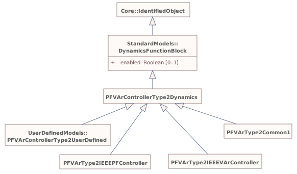
Destination
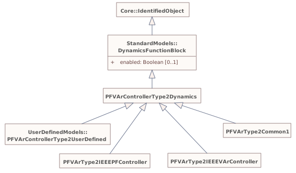
▶VoltageCompensatorDynamicsi
{7FD04580-1444-4ea3-A69D-D2D00000A4A9}
Package notes
<font color="#0f0f0f">Synchronous machine terminal voltage transducer and current compensator models</font> adjust the terminal voltage feedback to the excitation system by adding a quantity that is proportional to the terminal current of the generator. It is linked to a specific generator (synchronous machine).
<font color="#0f0f0f">Several types of compensation are available on most excitation systems. Synchronous machine active and reactive current compensation are the most common. Either reactive droop compensation and/or line-drop compensation can be used, simulating an impedance drop and effectively regulating at some point other than the terminals of the machine. The impedance or range of adjustment and type of compensation should be specified for different types. </font>
<font color="#0f0f0f">Care shall be taken to ensure that a consistent PU system is utilized for the compensator parameters and the synchronous machine current base.</font>
<font color="#0f0f0f">For further information see IEEE 421.5-2005, 4.</font>
<font color="#0f0f0f">
</font>Package metadata — changes
| Baseline | Destination | |
|---|---|---|
| no changes | ||
Tagged values — changes
| Baseline | Destination | |
|---|---|---|
| no changes | ||
Package notes
<font color="#0f0f0f">Synchronous machine terminal voltage transducer and current compensator models</font> adjust the terminal voltage feedback to the excitation system by adding a quantity that is proportional to the terminal current of the generator. It is linked to a specific generator (synchronous machine).
<font color="#0f0f0f">Several types of compensation are available on most excitation systems. Synchronous machine active and reactive current compensation are the most common. Either reactive droop compensation and/or line-drop compensation can be used, simulating an impedance drop and effectively regulating at some point other than the terminals of the machine. The impedance or range of adjustment and type of compensation should be specified for different types. </font>
<font color="#0f0f0f">Care shall be taken to ensure that a consistent PU system is utilized for the compensator parameters and the synchronous machine current base.</font>
<font color="#0f0f0f">For further information see IEEE 421.5-2005, 4.</font>
<font color="#0f0f0f">
</font>Package 'VoltageCompensatorDynamics' has no changes to the 4 classes it contains.
Changed diagrams (1)
▶▦VoltageCompensatorDynamicsi
CHANGED{107B566B-D071-4cc9-B058-F986EB9B14D5}
Diagram notes
This diagram shows dynamic standard model voltage compensator classes and their inheritance from the VoltageCompensatorDynamics class.Diagram metadata — changes
| Baseline | Destination | |
|---|---|---|
| no changes | ||
Diagram notes
This diagram shows dynamic standard model voltage compensator classes and their inheritance from the VoltageCompensatorDynamics class.▦Diagram
changed
Baseline
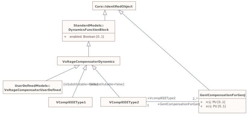
Destination
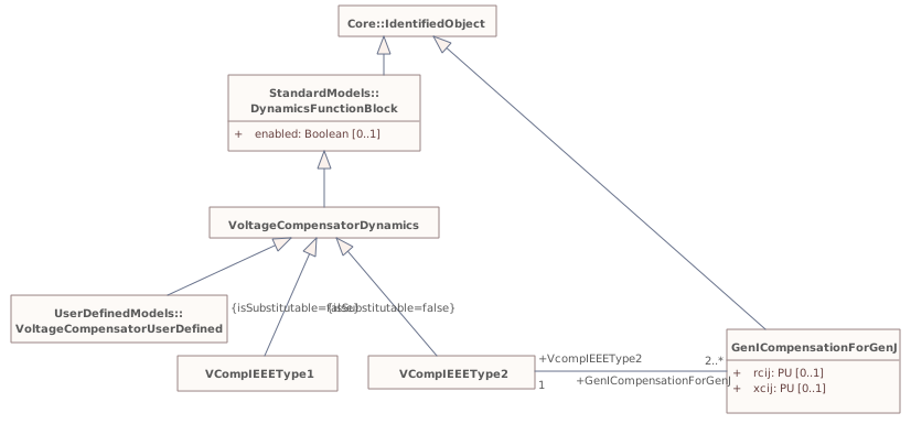
▶HVDCDynamicsi
{7C62349B-D355-4ba0-BE12-91068427292A}
Package notes
High voltage direct current (HVDC) models.Package metadata — changes
| Baseline | Destination | |
|---|---|---|
| no changes | ||
Tagged values — changes
| Baseline | Destination | |
|---|---|---|
| no changes | ||
Package notes
High voltage direct current (HVDC) models.Package 'HVDCDynamics' has no changes to the 3 classes it contains.
Changed diagrams (1)
▶▦HVDCDynamicsi
CHANGED{CE7EEDFF-0F31-40bd-A1D7-85C44EC39CDE}
Diagram notes
This diagram shows the dynamics model classes related to modelling of the HVDC.Diagram metadata — changes
| Baseline | Destination | |
|---|---|---|
| no changes | ||
Diagram notes
This diagram shows the dynamics model classes related to modelling of the HVDC.▦Diagram
changed
Baseline
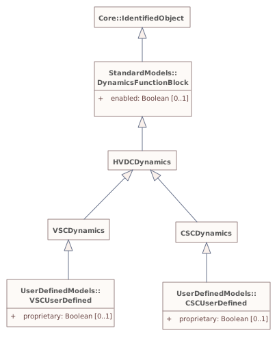
Destination
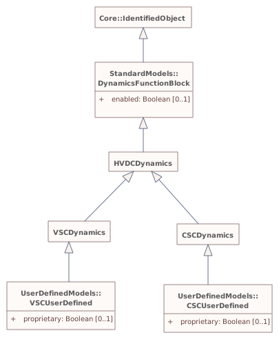
▶StaticVarCompensatorDynamicsi
{97871C31-9D61-4b9b-A49A-F63A7DC2DBA5}
Package notes
Static var compensator (SVC) models.Package metadata — changes
| Baseline | Destination | |
|---|---|---|
| no changes | ||
Tagged values — changes
| Baseline | Destination | |
|---|---|---|
| no changes | ||
Package notes
Static var compensator (SVC) models.Package 'StaticVarCompensatorDynamics' has no changes to the 1 classes it contains.
Changed diagrams (1)
▶▦StaticVarCompensatorDynamicsi
CHANGED{94AF0B28-6DC7-475c-9559-0CAC69363500}
Diagram notes
This diagram shows the dynamics model classes related to modelling of the static var compensator (SVC) models.Diagram metadata — changes
| Baseline | Destination | |
|---|---|---|
| no changes | ||
Diagram notes
This diagram shows the dynamics model classes related to modelling of the static var compensator (SVC) models.▦Diagram
changed
Baseline
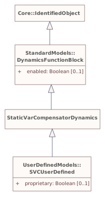
Destination
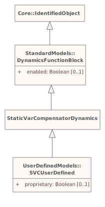
Package 'StandardModels' has no changes to the 2 classes it contains.
▶InfIEC61970i
{D2DD87AA-AF0C-477c-8E65-69D543D76521}
Package notes
This package and its subpackages contain informative (unstable) elements of the model, expected to evolve a lot or to be removed, and not published as IEC document yet. Some portions of it will be reworked and moved to normative packages as the need arises, and some portions may be removed.
WG13 does not generate documentation for this informative portion of the model.Package metadata — changes
| Baseline | Destination | |
|---|---|---|
| no changes | ||
Tagged values — changes
| Baseline | Destination | |
|---|---|---|
| no changes | ||
Package notes
This package and its subpackages contain informative (unstable) elements of the model, expected to evolve a lot or to be removed, and not published as IEC document yet. Some portions of it will be reworked and moved to normative packages as the need arises, and some portions may be removed.
WG13 does not generate documentation for this informative portion of the model.▶InfSIPSi
{BB903AB3-D08C-4d30-A5AE-E3FA868711FA}
Package notes
System Integrity Protection Schemes (SIPS) (IEC terminology). Other names used are: Remedial Action Schemes (RAS) or System Protection Schemes (SPS).Package metadata — changes
| Baseline | Destination | |
|---|---|---|
| no changes | ||
Tagged values — changes
| Baseline | Destination | |
|---|---|---|
| no changes | ||
Package notes
System Integrity Protection Schemes (SIPS) (IEC terminology). Other names used are: Remedial Action Schemes (RAS) or System Protection Schemes (SPS).Package 'InfSIPS' has no changes to the 26 classes it contains.
Changed diagrams (1)
▶▦RASInheritancei
CHANGED{35E945F1-DE75-4233-9318-EA2DCCB57A18}
Diagram notes
No notes defined in the model.Diagram metadata — changes
| Baseline | Destination | |
|---|---|---|
| no changes | ||
Diagram notes
No notes defined in the model.▦Diagram
changed
Baseline
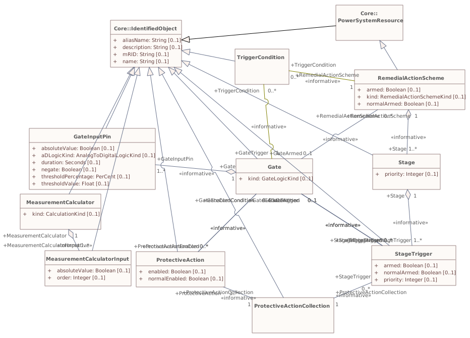
Destination
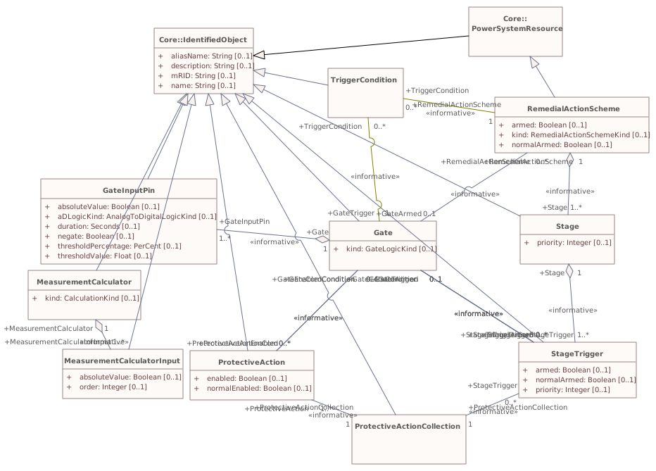
▶InfPart303i
{500389E9-5C8C-40f4-9EB4-19613576509E}
Package notes
No notes defined in the model.Package metadata — changes
| Baseline | Destination | |
|---|---|---|
| no changes | ||
Tagged values — changes
| Baseline | Destination | |
|---|---|---|
| no changes | ||
Package notes
No notes defined in the model.▶NetworkModelFramesi
{2C9E3B69-563C-4663-96DD-0E1074BE5F73}
Package notes
No notes defined in the model.Package metadata — changes
| Baseline | Destination | |
|---|---|---|
| no changes | ||
Tagged values — changes
| Baseline | Destination | |
|---|---|---|
| no changes | ||
Package notes
No notes defined in the model.Package 'NetworkModelFrames' has no changes to the 14 classes it contains.
Changed diagrams (1)
▶▦Framesi
CHANGED{9AE9BC65-CE60-4818-BCA9-8D6A8511D1C7}
Diagram notes
No notes defined in the model.Diagram metadata — changes
| Baseline | Destination | |
|---|---|---|
| no changes | ||
Diagram notes
No notes defined in the model.▦Diagram
changed
Baseline
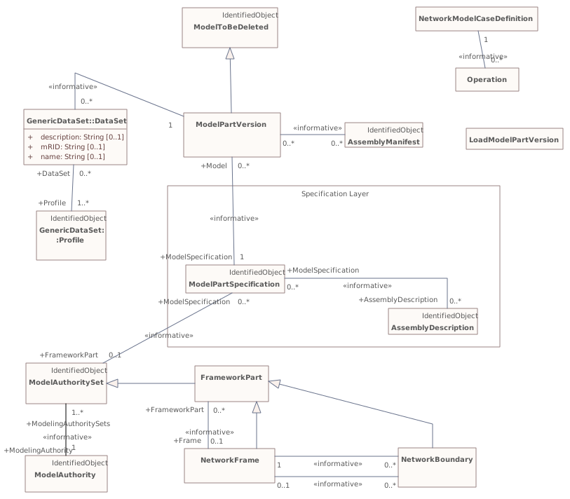
Destination
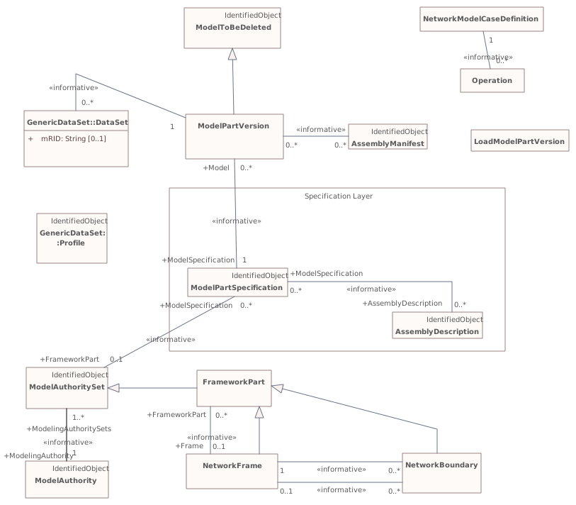
Connectors 1 removedhover a connector to outline the elements it joins
removedDataSet – Profile
▶NetworkModelProjectsi
{0090ED2A-A4A9-40f2-B6AC-02BBFADFE48D}
Package notes
Defining meta-data for a change set in the functional Power System model.Package metadata — changes
| Baseline | Destination | |
|---|---|---|
| no changes | ||
Tagged values — changes
| Baseline | Destination | |
|---|---|---|
| no changes | ||
Package notes
Defining meta-data for a change set in the functional Power System model.Package 'NetworkModelProjects' has no changes to the 19 classes it contains.
Changed diagrams (2)
▶▦InfPowerSystemProjectsPJMi
CHANGED{AAA4A8EE-D7BF-41c1-8611-15C1D784E506}
Diagram notes
No notes defined in the model.Diagram metadata — changes
| Baseline | Destination | |
|---|---|---|
| no changes | ||
Diagram notes
No notes defined in the model.▦Diagram
changed
Baseline
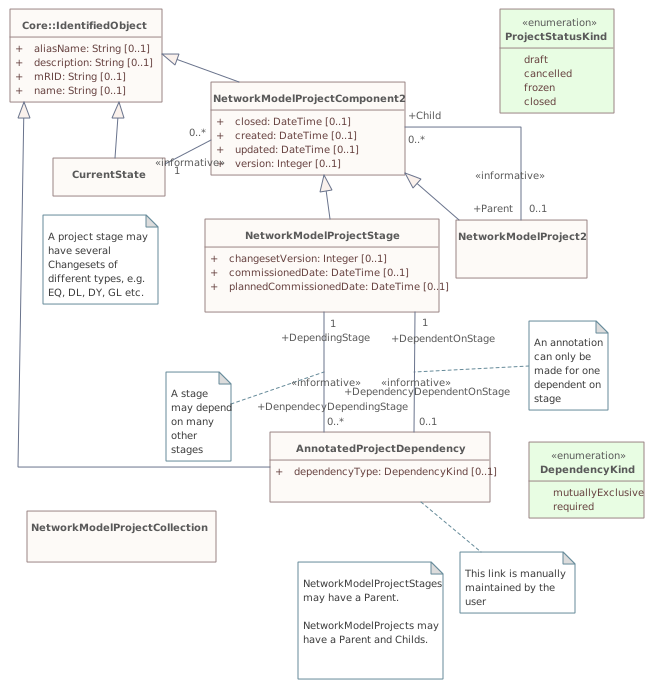
Destination
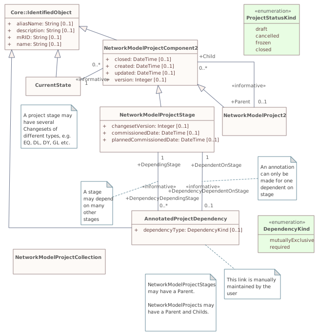
▶▦PowerSystemProjectDiscussioni
CHANGED{4BA9AD4C-A0FC-4df6-B473-0BDF19FA1F70}
Diagram notes
No notes defined in the model.Diagram metadata — changes
| Baseline | Destination | |
|---|---|---|
| no changes | ||
Diagram notes
No notes defined in the model.▦Diagram
changed
Baseline
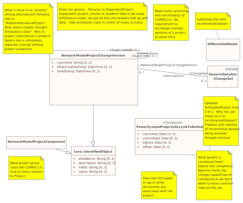
Destination
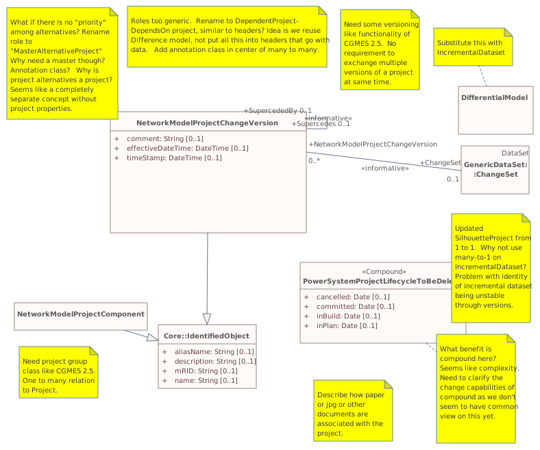
Package 'InfIEC61970' has no changes to the 1 diagrams it contains.
Changed classes (1)
▶⚙IEC61970CIMVersioni
CHANGED{990AB50C-5CF8-46d2-B5FF-887BBBD3346F}
Class notes
This is the IEC 61970 CIM version number assigned to this UML model.Class metadata — changes
| Baseline | Destination | |
|---|---|---|
| no changes | ||
Tagged values — changes
| Baseline | Destination | |
|---|---|---|
| no changes | ||
Class notes
This is the IEC 61970 CIM version number assigned to this UML model.≡Attributes
| Attribute | Baseline | Destination | Notes (destination, redlined) | ||||||||||||
|---|---|---|---|---|---|---|---|---|---|---|---|---|---|---|---|
| dateimetadata changed - hovermetadata changed{8DADB97F-283D-40c7-A25A-D75E4C0D8507}show details | Date [0..1] | Date [0..1] | Form is YYYY-MM-DD for example for January 5, 2009 it is 2009-01-05. | ||||||||||||
Attribute notes Form is YYYY-MM-DD for example for January 5, 2009 it is 2009-01-05.Attribute metadata — changes
Tagged values — changes
| |||||||||||||||
| versionimetadata changed - hovermetadata changed{B4E0B1B6-8794-406a-A4C6-CBB395E37A52}show details | String [0..1] | String [0..1] | Form is IEC61970CIMXXvYY where XX is the major CIM package version and the YY is the minor version. For example IEC61970CIM13v18. | ||||||||||||
Attribute notes Form is IEC61970CIMXXvYY where XX is the major CIM package version and the YY is the minor version. For example IEC61970CIM13v18.Attribute metadata — changes
Tagged values — changes
| |||||||||||||||
Changed diagrams (1)
▶▦IEC61970Dependenciesi
CHANGED{FB07D92D-5F4D-4fdc-AD82-2376FAF51037}
Diagram notes
This diagram shows all 61970-301 packages and their logical dependencies.Diagram metadata — changes
| Baseline | Destination | |
|---|---|---|
| ModifiedDate | 2019-09-21 20:26:39 | 2021-09-29 11:05:23 |
Diagram notes
This diagram shows all 61970-301 packages and their logical dependencies.▤Metadata
| Baseline | Destination | |
|---|---|---|
| ModifiedDate | 2019-09-21 20:26:39 | 2021-09-29 11:05:23 |
▦Diagram
addedmoved or resized
Baseline
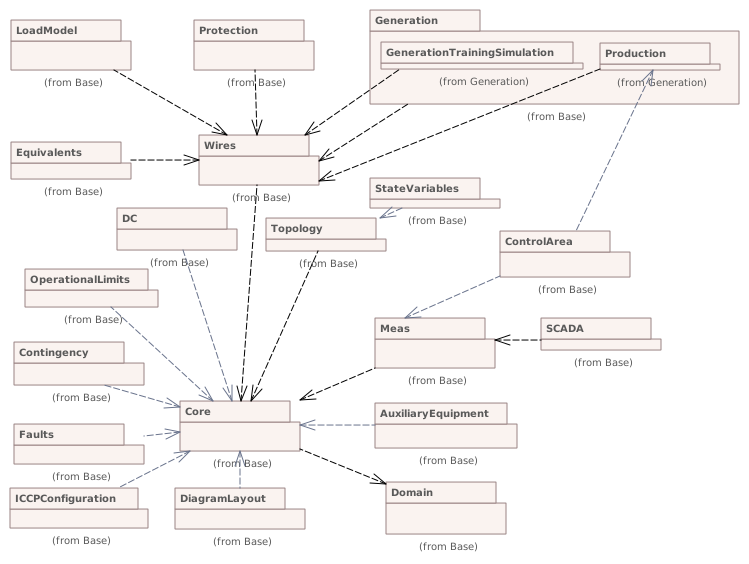
Destination
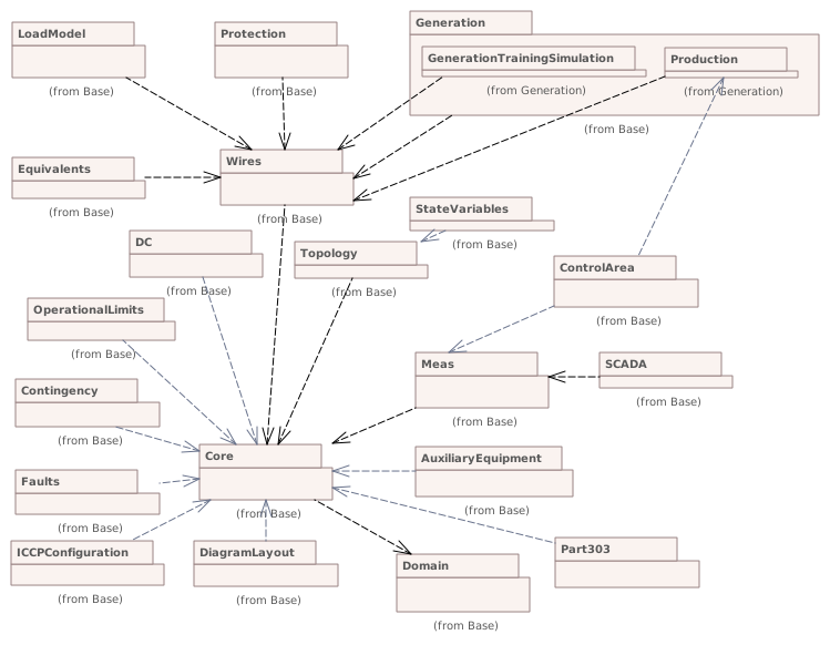
Connectors 1 added · 1 reroutedhover a connector to outline the elements it joins
added(not in this model) – (not in this model)
rerouted(not in this model) – (not in this model)