Classes2 added70 changed
Diagrams15 changed
Click a count to show only those itemspAdded — only in destinationDeleted — only in baselineMoved — same GUID, different packageChanged — same GUID and package; properties or members differIdenticalPackage (unchanged itself)struckinserted — destination text with baseline wording struck (notes, role notes, role names, multiplicities); the shows the notes and every changed propertyBlue — a changed attribute type (the new type)
▶IEC61970i
{21D32832-FF64-4213-B81C-55ACE35EEBFF}
Package notes
Top package for IEC 61970.Package metadata — changes
| Baseline | Destination | |
|---|---|---|
| no changes | ||
Tagged values — changes
| Baseline | Destination | |
|---|---|---|
| no changes | ||
Package notes
Top package for IEC 61970.▶Basei
{20A2C6D8-4765-466f-AD75-5E1B3CAF4E8D}
Package notes
Content of the base CIM published as IEC 61970-301.Package metadata — changes
| Baseline | Destination | |
|---|---|---|
| no changes | ||
Tagged values — changes
| Baseline | Destination | |
|---|---|---|
| no changes | ||
Package notes
Content of the base CIM published as IEC 61970-301.▶Domaini
{0134E45C-F32A-4522-A725-E07B0AE4CB57}
Package notes
The domain package defines primitive datatypes that are used by classes in other packages. Stereotypes are used to describe the datatypes. The following stereotypes are defined:
<<enumeration>> A list of permissible constant values.
<<Primitive>> The most basic data types used to compose all other data types.
<<CIMDatatype>> A datatype that contains a value attribute, an optional unit of measure and a unit multiplier. The unit and multiplier may be specified as a static variable initialized to the allowed value.
<<Compound>> A composite of Primitive, enumeration, CIMDatatype or other Compound classes, as long as the Compound classes do not recurse.
For all datatypes both positive and negative values are allowed unless stated otherwise for a particular datatype.Package metadata — changes
| Baseline | Destination | |
|---|---|---|
| no changes | ||
Tagged values — changes
| Baseline | Destination | |
|---|---|---|
| no changes | ||
Package notes
The domain package defines primitive datatypes that are used by classes in other packages. Stereotypes are used to describe the datatypes. The following stereotypes are defined:
<<enumeration>> A list of permissible constant values.
<<Primitive>> The most basic data types used to compose all other data types.
<<CIMDatatype>> A datatype that contains a value attribute, an optional unit of measure and a unit multiplier. The unit and multiplier may be specified as a static variable initialized to the allowed value.
<<Compound>> A composite of Primitive, enumeration, CIMDatatype or other Compound classes, as long as the Compound classes do not recurse.
For all datatypes both positive and negative values are allowed unless stated otherwise for a particular datatype.Changed classes (3)
▶⚙PerCent«CIMDatatype»i For example, specify as 100 to indicate at the defined base.
CHANGED{8345A4E0-E4BB-45d6-894B-983BB43C4B4F}
Class notes (destination, redlined)
Percentage on a defined base.Class metadata — changes
| Baseline | Destination | |
|---|---|---|
| no changes | ||
Tagged values — changes
| Baseline | Destination | |
|---|---|---|
| no changes | ||
Class notes (destination, redlined)
Percentage on a defined base.Class 'PerCent' has no other changes. The shows its notes and every changed property.
▶⚙UnitMultiplier«enumeration»i When applied to unit symbols, the unit symbol is treated as a derived unit. Regardless of the contents of the unit symbol text, the unit symbol shall be treated as if it were a single-character unit symbol. Unit symbols should not contain multipliers, and it should be left to the multiplier to define the multiple for an entire data type.
For example, if a unit symbol is "m2Pers" and the multiplier is "k", then the value is k(m**2/s), and the multiplier applies to the entire final value, not to any individual part of the value. This can be conceptualized by substituting a derived unit symbol for the unit type. If one imagines that the symbol "Þ" represents the derived unit "m2Pers", then applying the multiplier "k" can be conceptualized simply as "kÞ".
For example, the SI unit for mass is "kg" and not "g". If the unit symbol is defined as "kg", then the multiplier is applied to "kg" as a whole and does not replace the "k" in front of the "g". In this case, the multiplier of "m" would be used with the unit symbol of "kg" to represent one gram. As a text string, this violates the instructions in IEC 80000-1. However, because the unit symbol in CIM is treated as a derived unit instead of as an SI unit, it makes more sense to conceptualize the "kg" as if it were replaced by one of the proposed replacements for the SI mass symbol. If one imagines that the "kg" were replaced by a symbol "Þ", then it is easier to conceptualize the multiplier "m" as creating the proper unit "mÞ", and not the forbidden unit "mkg".
CHANGED{DC62CC93-2E3F-4b9c-9C81-C84C30A6C67D}
Class notes (destination, redlined)
The unit multipliers defined for the CIM.Class metadata — changes
| Baseline | Destination | |
|---|---|---|
| no changes | ||
Tagged values — changes
| Baseline | Destination | |
|---|---|---|
| no changes | ||
Class notes (destination, redlined)
The unit multipliers defined for the CIM.Class 'UnitMultiplier' has no other changes. The shows its notes and every changed property.
▶⚙UnitSymbol«enumeration»i
CHANGED{80012160-A038-43b5-BA6F-9862E525518C}
Class notes
The derived units defined for usage in the CIM. In some cases, the derived unit is equal to an SI unit. Whenever possible, the standard derived symbol is used instead of the formula for the derived unit. For example, the unit symbol Farad is defined as "F" instead of "CPerV". In cases where a standard symbol does not exist for a derived unit, the formula for the unit is used as the unit symbol. For example, density does not have a standard symbol and so it is represented as "kgPerm3". With the exception of the "kg", which is an SI unit, the unit symbols do not contain multipliers and therefore represent the base derived unit to which a multiplier can be applied as a whole.
Every unit symbol is treated as an unparseable text as if it were a single-letter symbol. The meaning of each unit symbol is defined by the accompanying descriptive text and not by the text contents of the unit symbol.
To allow the widest possible range of serializations without requiring special character handling, several substitutions are made which deviate from the format described in IEC 80000-1. The division symbol "/" is replaced by the letters "Per". Exponents are written in plain text after the unit as "m3" instead of being formatted as "m" with a superscript of 3 or introducing a symbol as in "m^3". The degree symbol "°" is replaced with the letters "deg". Any clarification of the meaning for a substitution is included in the description for the unit symbol.
Non-SI units are included in list of unit symbols to allow sources of data to be correctly labelled with their non-SI units (for example, a GPS sensor that is reporting numbers that represent feet instead of meters). This allows software to use the unit symbol information correctly convert and scale the raw data of those sources into SI-based units.
The integer values are used for harmonization with IEC 61850.Class metadata — changes
| Baseline | Destination | |
|---|---|---|
| no changes | ||
Tagged values — changes
| Baseline | Destination | |
|---|---|---|
| no changes | ||
Class notes
The derived units defined for usage in the CIM. In some cases, the derived unit is equal to an SI unit. Whenever possible, the standard derived symbol is used instead of the formula for the derived unit. For example, the unit symbol Farad is defined as "F" instead of "CPerV". In cases where a standard symbol does not exist for a derived unit, the formula for the unit is used as the unit symbol. For example, density does not have a standard symbol and so it is represented as "kgPerm3". With the exception of the "kg", which is an SI unit, the unit symbols do not contain multipliers and therefore represent the base derived unit to which a multiplier can be applied as a whole.
Every unit symbol is treated as an unparseable text as if it were a single-letter symbol. The meaning of each unit symbol is defined by the accompanying descriptive text and not by the text contents of the unit symbol.
To allow the widest possible range of serializations without requiring special character handling, several substitutions are made which deviate from the format described in IEC 80000-1. The division symbol "/" is replaced by the letters "Per". Exponents are written in plain text after the unit as "m3" instead of being formatted as "m" with a superscript of 3 or introducing a symbol as in "m^3". The degree symbol "°" is replaced with the letters "deg". Any clarification of the meaning for a substitution is included in the description for the unit symbol.
Non-SI units are included in list of unit symbols to allow sources of data to be correctly labelled with their non-SI units (for example, a GPS sensor that is reporting numbers that represent feet instead of meters). This allows software to use the unit symbol information correctly convert and scale the raw data of those sources into SI-based units.
The integer values are used for harmonization with IEC 61850.≡Attributes
| Attribute | Baseline | Destination | Notes (destination, redlined) | ||||||||||||
|---|---|---|---|---|---|---|---|---|---|---|---|---|---|---|---|
| kgi{E8CD3F4B-2301-4f19-BBDF-6D20CD945743}show details | [1..1] | [1..1] | Mass in kilograms. | ||||||||||||
Attribute notes (destination, redlined) Mass in kilograms.Attribute metadata — changes
Tagged values — changes
| |||||||||||||||
Package 'Domain' has no changes to the 7 diagrams it contains.
▶Corei
{6A503B72-6E15-4cd1-B92D-DDF6D14DBE29}
Package notes
Contains the core PowerSystemResource and ConductingEquipment entities shared by all applications plus common collections of those entities. Not all applications require all the Core entities. This package does not depend on any other package except the Domain package, but most of the other packages have associations and generalizations that depend on it.Package metadata — changes
| Baseline | Destination | |
|---|---|---|
| no changes | ||
Tagged values — changes
| Baseline | Destination | |
|---|---|---|
| no changes | ||
Package notes
Contains the core PowerSystemResource and ConductingEquipment entities shared by all applications plus common collections of those entities. Not all applications require all the Core entities. This package does not depend on any other package except the Domain package, but most of the other packages have associations and generalizations that depend on it.Added classes (2)
▶⚙NamingAuthorityi
ADDED{DB6818FE-9B52-4c48-8D64-82133875B67E}
Class notes
Authority responsible for creation and management of names of a given name type and/or name; typically an organization or an enterprise system.Class metadata — changes
| Baseline | Destination | |
|---|---|---|
| Abstract | false | |
| Author | tviegut | |
| Complexity | 1 | |
| GenType | Java | |
| IsLeaf | false | |
| IsRoot | false | |
| IsSpec | false | |
| Name | NamingAuthority | |
| ParentPackage | Core | |
| Phase | 1.0 | |
| Scope | public | |
| Status | Proposed | |
| Type | Class | |
| Version | 1.0 |
Tagged values — changes
| Baseline | Destination | |
|---|---|---|
| none | ||
Class notes
Authority responsible for creation and management of names of a given name type and/or name; typically an organization or an enterprise system.▤Metadata
| Baseline | Destination | |
|---|---|---|
| Abstract | false | |
| Author | tviegut | |
| Complexity | 1 | |
| GenType | Java | |
| IsLeaf | false | |
| IsRoot | false | |
| IsSpec | false | |
| Name | NamingAuthority | |
| ParentPackage | Core | |
| Phase | 1.0 | |
| Scope | public | |
| Status | Proposed | |
| Type | Class | |
| Version | 1.0 |
≡Attributes
| Attribute | Baseline | Destination | Notes (destination, redlined) | |||||||||||||||||||||||||||||||||||||||||||||
|---|---|---|---|---|---|---|---|---|---|---|---|---|---|---|---|---|---|---|---|---|---|---|---|---|---|---|---|---|---|---|---|---|---|---|---|---|---|---|---|---|---|---|---|---|---|---|---|---|
| descriptioni{3A8F279F-D318-4248-B54F-1DCBD9214683}show details | did not exist | String [0..1] | Description of the naming authority. | |||||||||||||||||||||||||||||||||||||||||||||
Attribute notes Description of the naming authority.Attribute metadata — changes
Tagged values — changes
| ||||||||||||||||||||||||||||||||||||||||||||||||
| mRIDi{272201FC-E663-4924-98B0-719B7F305C60}show details | did not exist | String [0..1] | Master resource identifier issued by a model authority. The mRID is unique within an exchange context. Global uniqueness is easily achieved by using a UUID, as specified in RFC 4122, for the mRID. The use of UUID is strongly recommended. For CIMXML data files in RDF syntax conforming to IEC 61970-552, the mRID is mapped to rdf:ID or rdf:about attributes that identify CIM object elements. | |||||||||||||||||||||||||||||||||||||||||||||
Attribute notes Master resource identifier issued by a model authority. The mRID is unique within an exchange context. Global uniqueness is easily achieved by using a UUID, as specified in RFC 4122, for the mRID. The use of UUID is strongly recommended.
For CIMXML data files in RDF syntax conforming to IEC 61970-552, the mRID is mapped to rdf:ID or rdf:about attributes that identify CIM object elements.Attribute metadata — changes
Tagged values — changes
| ||||||||||||||||||||||||||||||||||||||||||||||||
| namei{0C006194-17C9-496c-9E58-10A82B42A56D}show details | did not exist | String [0..1] | Name of the naming authority. | |||||||||||||||||||||||||||||||||||||||||||||
Attribute notes Name of the naming authority.Attribute metadata — changes
Tagged values — changes
| ||||||||||||||||||||||||||||||||||||||||||||||||
⇄Links
ADDEDAssociation{111511FB-1615-4322-9183-133852DE3835}
Baselinedid not exist
→
Link metadata
| Baseline | Destination | |
|---|---|---|
| Direction | Unspecified | |
| IsLeaf | false | |
| IsRoot | false | |
| Type | Association |
Source end
| Baseline | Destination | |
|---|---|---|
| Cardinality | 0..1 | |
| Containment | Unspecified | |
| End | Naming | |
| IsAggregation | none | |
| IsChangeable | none | |
| IsNavigable | true | |
| Ordering | false | |
| Role | Naming | |
| RoleNote | All name types managed by this authority. | |
| Scope | public | |
| TargetScope | instance |
Target end
| Baseline | Destination | |
|---|---|---|
| Cardinality | 0..* | |
| Containment | Unspecified | |
| End | Name | |
| IsAggregation | none | |
| IsChangeable | none | |
| IsNavigable | true | |
| Ordering | false | |
| Role | Name | |
| RoleNote | Authority responsible for managing this name type. | |
| Scope | public | |
| TargetScope | instance |
ADDEDAssociation{6E9C6A1A-D006-4e6d-B31F-02A38090899F}
Baselinedid not exist
→
Link metadata
| Baseline | Destination | |
|---|---|---|
| Direction | Unspecified | |
| IsLeaf | false | |
| IsRoot | false | |
| Type | Association |
Source end
| Baseline | Destination | |
|---|---|---|
| Cardinality | 0..1 | |
| Containment | Unspecified | |
| End | Naming | |
| IsAggregation | none | |
| IsChangeable | none | |
| IsNavigable | true | |
| Ordering | false | |
| Role | Naming | |
| RoleNote | All names managed by this authority. | |
| Scope | public | |
| TargetScope | instance |
Target end
| Baseline | Destination | |
|---|---|---|
| Cardinality | 0..* | |
| Containment | Unspecified | |
| End | Name | |
| IsAggregation | none | |
| IsChangeable | none | |
| IsNavigable | true | |
| Ordering | false | |
| Role | Name | |
| RoleNote | Authority responsible for managing this name. | |
| Scope | public | |
| TargetScope | instance |
▶⚙ObjectTypei
ADDED{DD569691-4FED-4775-8631-C48D2192912A}
Class notes
Identifies the specialised type of an object when the instance object is serialised using a generalised class. It may be useful when the object type is not otherwise included in the exchange. For example, a Meter may be serialised as an EndDevice in message exchanges and need to have the ObjectType.type be specified as 'Meter' to provide context to the message receiver.Class metadata — changes
| Baseline | Destination | |
|---|---|---|
| Abstract | false | |
| Author | tviegut | |
| Complexity | 1 | |
| GenType | Java | |
| IsLeaf | false | |
| IsRoot | false | |
| IsSpec | false | |
| Name | ObjectType | |
| ParentPackage | Core | |
| Phase | 1.0 | |
| Scope | public | |
| Status | Proposed | |
| Type | Class | |
| Version | 1.0 |
Tagged values — changes
| Baseline | Destination | |
|---|---|---|
| none | ||
Class notes
Identifies the specialised type of an object when the instance object is serialised using a generalised class. It may be useful when the object type is not otherwise included in the exchange. For example, a Meter may be serialised as an EndDevice in message exchanges and need to have the ObjectType.type be specified as 'Meter' to provide context to the message receiver.▤Metadata
| Baseline | Destination | |
|---|---|---|
| Abstract | false | |
| Author | tviegut | |
| Complexity | 1 | |
| GenType | Java | |
| IsLeaf | false | |
| IsRoot | false | |
| IsSpec | false | |
| Name | ObjectType | |
| ParentPackage | Core | |
| Phase | 1.0 | |
| Scope | public | |
| Status | Proposed | |
| Type | Class | |
| Version | 1.0 |
≡Attributes
| Attribute | Baseline | Destination | Notes (destination, redlined) | |||||||||||||||||||||||||||||||||||||||||||||
|---|---|---|---|---|---|---|---|---|---|---|---|---|---|---|---|---|---|---|---|---|---|---|---|---|---|---|---|---|---|---|---|---|---|---|---|---|---|---|---|---|---|---|---|---|---|---|---|---|
| typei{70E04254-C620-4108-9F63-0A1DF9C9295F}show details | did not exist | String [0..1] | ||||||||||||||||||||||||||||||||||||||||||||||
Attribute notes No notes defined in the model.Attribute metadata — changes
Tagged values — changes
| ||||||||||||||||||||||||||||||||||||||||||||||||
⇄Links
ADDEDAssociation{3C5A5B2C-87E7-43fa-BAE4-3A2EF7409D72}
Baselinedid not exist
→
Link metadata
| Baseline | Destination | |
|---|---|---|
| Direction | Unspecified | |
| IsLeaf | false | |
| IsRoot | false | |
| Type | Association |
Source end
| Baseline | Destination | |
|---|---|---|
| Cardinality | 0..1 | |
| Containment | Unspecified | |
| End | Object | |
| IsAggregation | none | |
| IsChangeable | none | |
| IsNavigable | true | |
| Ordering | false | |
| Role | Object | |
| RoleNote | The object type of the Identified | |
| Scope | public | |
| TargetScope | instance |
Target end
| Baseline | Destination | |
|---|---|---|
| Cardinality | 0..* | |
| Containment | Unspecified | |
| End | Identified | |
| IsAggregation | none | |
| IsChangeable | none | |
| IsNavigable | true | |
| Ordering | false | |
| Role | Identified | |
| RoleNote | The Identified | |
| Scope | public | |
| TargetScope | instance |
Changed classes (16)
▶⚙ACDCTerminali
CHANGED{D37077B9-3B0C-4c16-8F5F-9A6F2C83A7F2}
Class notes
An electrical connection point (AC or DC) to a piece of conducting equipment. Terminals are connected at physical connection points called connectivity nodes.Class metadata — changes
| Baseline | Destination | |
|---|---|---|
| no changes | ||
Tagged values — changes
| Baseline | Destination | |
|---|---|---|
| no changes | ||
Class notes
An electrical connection point (AC or DC) to a piece of conducting equipment. Terminals are connected at physical connection points called connectivity nodes.≡Attributes
| Attribute | Baseline | Destination | Notes (destination, redlined) | ||||||||||||
|---|---|---|---|---|---|---|---|---|---|---|---|---|---|---|---|
| connectedi{C97C0B38-C62F-4f03-A3DE-A67F29A6C6DB}show details | Boolean [0..1] | Boolean [0..1] | The connected status is related to a bus-branch model and the topological node to terminal relation. | ||||||||||||
Attribute notes (destination, redlined) The connected status is related to a bus-branch model and the topological node to terminal relation.Attribute metadata — changes
Tagged values — changes
| |||||||||||||||
| sequenceNumberi{7C7195D3-DFCD-487f-BF92-F359BBE7AFD0}show details | Integer [0..1] | Integer [0..1] | The orientation of the terminal connections for a multiple terminal conducting equipment. | ||||||||||||
Attribute notes (destination, redlined) The orientation of the terminal connections for a multiple terminal conducting equipment.Attribute metadata — changes
Tagged values — changes
| |||||||||||||||
▶⚙BaseVoltagei
CHANGED{2E70DC9D-AEAE-46cc-B20A-C20A636AE9B0}
Class notes
Defines a system base voltage which is referenced.Class metadata — changes
| Baseline | Destination | |
|---|---|---|
| no changes | ||
Tagged values — changes
| Baseline | Destination | |
|---|---|---|
| no changes | ||
Class notes
Defines a system base voltage which is referenced.≡Attributes
| Attribute | Baseline | Destination | Notes (destination, redlined) | ||||||||||||
|---|---|---|---|---|---|---|---|---|---|---|---|---|---|---|---|
| nominalVoltagei{D37DA22A-916B-4a33-88AB-B77C229DB882}show details | Voltage [0..1] | Voltage [0..1] | The power system resource's base voltage. | ||||||||||||
Attribute notes (destination, redlined) The power system resource's base voltage.Attribute metadata — changes
Tagged values — changes
| |||||||||||||||
⇄Links
CHANGEDAssociation{DEF1E6AE-B7B9-43bf-9A91-E4BFC453DC4D}
→
Source end — TransformerEnds
| Baseline | Destination | |
|---|---|---|
| RoleNote | Transformer ends at the base voltage. This is essential for PU calculation. | Transformer ends at the base voltage. |
Target end — BaseVoltage
| Baseline | Destination | |
|---|---|---|
| RoleNote | Base voltage of the transformer end. This is essential for PU calculation. | Base voltage of the transformer end. |
▶⚙BasicIntervalSchedulei
CHANGED{848DEDB2-99A8-44ec-8319-F7629519D147}
Class notes
Schedule of values at points in time.Class metadata — changes
| Baseline | Destination | |
|---|---|---|
| no changes | ||
Tagged values — changes
| Baseline | Destination | |
|---|---|---|
| no changes | ||
Class notes
Schedule of values at points in time.≡Attributes
| Attribute | Baseline | Destination | Notes (destination, redlined) | ||||||||||||
|---|---|---|---|---|---|---|---|---|---|---|---|---|---|---|---|
| startTimei{3ACCE58A-16D7-4605-BA2E-BC0F2B4DDC51}show details | DateTime [0..1] | DateTime [0..1] | The time for the first time point. | ||||||||||||
Attribute notes (destination, redlined) The time for the first time point.Attribute metadata — changes
Tagged values — changes
| |||||||||||||||
▶⚙Bayi
CHANGED{45910062-D4E8-40ee-99EB-FEC14DD9FAB0}
Class notes
A collection of power system resources (within a given substation) including conducting equipment, protection relays, measurements, and telemetry. A bay typically represents a physical grouping related to modularization of equipment.Class metadata — changes
| Baseline | Destination | |
|---|---|---|
| no changes | ||
Tagged values — changes
| Baseline | Destination | |
|---|---|---|
| no changes | ||
Class notes
A collection of power system resources (within a given substation) including conducting equipment, protection relays, measurements, and telemetry. A bay typically represents a physical grouping related to modularization of equipment.▶⚙ConductingEquipmenti
CHANGED{7C5F19FB-5253-430c-8E53-BDCF7EBCE4C1}
Class notes
The parts of the AC power system that are designed to carry current or that are conductively connected through terminals.Class metadata — changes
| Baseline | Destination | |
|---|---|---|
| no changes | ||
Tagged values — changes
| Baseline | Destination | |
|---|---|---|
| no changes | ||
Class notes
The parts of the AC power system that are designed to carry current or that are conductively connected through terminals.⇄Links
CHANGEDAssociation{EEA2935F-26F1-463e-890E-676B5DDA189A}
→
Source end — Outage
| Baseline | Destination | |
|---|---|---|
| RoleNote | The outage that is isolated by the outage isolation equipment. | (empty) |
Target end — OutageIsolationEquipment
| Baseline | Destination | |
|---|---|---|
| RoleNote | The equipment that isolates this outage | (empty) |
▶⚙Curvei
CHANGED{73A500A6-E7FF-4abe-8FDA-E68B4E60FF9F}
Class notes
A multi-purpose curve or functional relationship between an independent variable (X-axis) and dependent (Y-axis) variables.Class metadata — changes
| Baseline | Destination | |
|---|---|---|
| no changes | ||
Tagged values — changes
| Baseline | Destination | |
|---|---|---|
| no changes | ||
Class notes
A multi-purpose curve or functional relationship between an independent variable (X-axis) and dependent (Y-axis) variables.⇄Links
CHANGEDAssociation{21D1EA17-DE1A-4a12-BCB8-293A9781EFC4}
→
Source end
no changes
Target end — Curve
| Baseline | Destination | |
|---|---|---|
| RoleNote | The curve of this curve data point. | The curve of |
▶⚙CurveDatai The use of this generic class is discouraged if a more specific class can be used to specify the X and Y axis values along with their specific data types.
CHANGED{49452B3C-BB66-4c7a-A86B-6BE155BB7193}
Class notes (destination, redlined)
Multi-purpose data points for defining a curve.Class metadata — changes
| Baseline | Destination | |
|---|---|---|
| no changes | ||
Tagged values — changes
| Baseline | Destination | |
|---|---|---|
| no changes | ||
Class notes (destination, redlined)
Multi-purpose data points for defining a curve.≡Attributes
| Attribute | Baseline | Destination | Notes (destination, redlined) | ||||||||||||
|---|---|---|---|---|---|---|---|---|---|---|---|---|---|---|---|
| xvaluei{25202638-FF67-4a74-9190-EFB0B473BAAB}show details | Float [0..1] | Float [0..1] | The data value of the X-axis variable, | ||||||||||||
Attribute notes (destination, redlined) The data value of the X-axis variable,Attribute metadata — changes
Tagged values — changes
| |||||||||||||||
⇄Links
CHANGEDAssociation{21D1EA17-DE1A-4a12-BCB8-293A9781EFC4}
→
Source end
no changes
Target end — Curve
| Baseline | Destination | |
|---|---|---|
| RoleNote | The curve of this curve data point. | The curve of |
▶⚙CurveStyle«enumeration»i
CHANGED{36FD838A-90B0-4634-A4F2-B6E431D246D7}
Class notes
Style or shape of curve.Class metadata — changes
| Baseline | Destination | |
|---|---|---|
| no changes | ||
Tagged values — changes
| Baseline | Destination | |
|---|---|---|
| no changes | ||
Class notes
Style or shape of curve.≡Attributes
| Attribute | Baseline | Destination | Notes (destination, redlined) | ||||||||||||
|---|---|---|---|---|---|---|---|---|---|---|---|---|---|---|---|
| straightLineYValuesi{C87B3CE1-F526-4e92-A292-0238CA829EA0}show details | [1..1] | [1..1] | The Y-axis values are assumed to be a straight line between values. | ||||||||||||
Attribute notes (destination, redlined) The Y-axis values are assumed to be a straight line between values.Attribute metadata — changes
Tagged values — changes
| |||||||||||||||
▶⚙Equipmenti
CHANGED{F8DD8DAC-3545-4660-9CA5-794881CC6591}
Class notes
The parts of a power system that are physical devices, electronic or mechanical.Class metadata — changes
| Baseline | Destination | |
|---|---|---|
| no changes | ||
Tagged values — changes
| Baseline | Destination | |
|---|---|---|
| no changes | ||
Class notes
The parts of a power system that are physical devices, electronic or mechanical.≡Attributes
| Attribute | Baseline | Destination | Notes (destination, redlined) | ||||||||||||
|---|---|---|---|---|---|---|---|---|---|---|---|---|---|---|---|
| aggregatei{3C000D48-C67D-4cc3-89D6-5F336420B325}show details | Boolean [0..1] | Boolean [0..1] | The aggregate flag provides an alternative way of representing an aggregated (equivalent) element. It is applicable in cases when the dedicated classes for equivalent equipment do not have all of the attributes necessary to represent the required level of detail. | ||||||||||||
Attribute notes (destination, redlined) The aggregate flag provides an alternative way of representing an aggregated (equivalent) element. It is applicable in cases when the dedicated classes for equivalent equipment do not have all of the attributes necessary to represent the required level of detail.Attribute metadata — changes
Tagged values — changes
| |||||||||||||||
▶⚙IdentifiedObjecti
CHANGED{055C5806-E9D8-4a7a-9307-DAF7C31763C7}
Class notes
This is a root class to provide common identification for all classes needing identification and naming attributes.Class metadata — changes
| Baseline | Destination | |
|---|---|---|
| no changes | ||
Tagged values — changes
| Baseline | Destination | |
|---|---|---|
| no changes | ||
Class notes
This is a root class to provide common identification for all classes needing identification and naming attributes.≡Attributes
| Attribute | Baseline | Destination | Notes (destination, redlined) | ||||||||||||
|---|---|---|---|---|---|---|---|---|---|---|---|---|---|---|---|
| aliasNamei{D4F8B75D-CDAD-4440-8092-1425101E5ABC}show details | String [0..1] | String [0..1] | The aliasName is free text human readable name of the object alternative to IdentifiedObject.name. It may be non unique and may not correlate to a naming hierarchy.
The attribute aliasName is retained because of backwards compatibility between CIM | ||||||||||||
Attribute notes (destination, redlined) The aliasName is free text human readable name of the object alternative to IdentifiedObject.name. It may be non unique and may not correlate to a naming hierarchy.
The attribute aliasName is retained because of backwards compatibility between CIM Attribute metadata — changes
Tagged values — changes
| |||||||||||||||
| mRIDi{C775F80A-A23D-4f38-AB9D-49D1FA882337}show details | String [0..1] | String [0..1] | Master resource identifier issued by a model authority. The mRID is unique within an exchange context. Global uniqueness is easily achieved by using a UUID, as specified in IETF RFC 4122, for the mRID. The use of UUID is strongly recommended. For CIMXML data files in RDF syntax conforming to IEC 61970-552, the mRID is mapped to rdf:ID or rdf:about attributes that identify CIM object elements. | ||||||||||||
Attribute notes (destination, redlined) Master resource identifier issued by a model authority. The mRID is unique within an exchange context. Global uniqueness is easily achieved by using a UUID, as specified in IETF RFC 4122, for the mRID. The use of UUID is strongly recommended.
For CIMXML data files in RDF syntax conforming to IEC 61970-552, the mRID is mapped to rdf:ID or rdf:about attributes that identify CIM object elements.Attribute metadata — changes
Tagged values — changes
| |||||||||||||||
⇄Links
CHANGEDAssociation{203C47E2-30FB-4c8f-ABEA-1661621CC0A7}
→
Source end — name
| Baseline | Destination | |
|---|---|---|
| Role | Names | name |
| RoleNote | All names of this identified object. | All names of this identified object. Names may be but are not guaranteed to be unique. |
Target end — IdentifiedObject
| Baseline | Destination | |
|---|---|---|
| Cardinality | 1 | 0..1 |
ADDEDAssociation{3C5A5B2C-87E7-43fa-BAE4-3A2EF7409D72}
Baselinedid not exist
→
Link metadata
| Baseline | Destination | |
|---|---|---|
| Direction | Unspecified | |
| IsLeaf | false | |
| IsRoot | false | |
| Type | Association |
Source end
| Baseline | Destination | |
|---|---|---|
| Cardinality | 0..1 | |
| Containment | Unspecified | |
| End | Object | |
| IsAggregation | none | |
| IsChangeable | none | |
| IsNavigable | true | |
| Ordering | false | |
| Role | Object | |
| RoleNote | The object type of the Identified | |
| Scope | public | |
| TargetScope | instance |
Target end
| Baseline | Destination | |
|---|---|---|
| Cardinality | 0..* | |
| Containment | Unspecified | |
| End | Identified | |
| IsAggregation | none | |
| IsChangeable | none | |
| IsNavigable | true | |
| Ordering | false | |
| Role | Identified | |
| RoleNote | The Identified | |
| Scope | public | |
| TargetScope | instance |
ADDEDAssociation{6989646B-A0B3-437e-8346-82B0944546F8}
Baselinedid not exist
→
DestinationName role AlternativeIdentifier [0..*] → IdentifiedObject role UniqueIdentifiedObject [0..1]
Link metadata
| Baseline | Destination | |
|---|---|---|
| Direction | Unspecified | |
| IsLeaf | false | |
| IsRoot | false | |
| Type | Association |
Source end
| Baseline | Destination | |
|---|---|---|
| Cardinality | 0..* | |
| Containment | Unspecified | |
| End | Name | |
| IsAggregation | none | |
| IsChangeable | none | |
| IsNavigable | true | |
| Ordering | false | |
| Role | Alternative | |
| RoleNote | All alternative identifiers of this identified object. No two identified objects can have the same alternative identifier. | |
| Scope | public | |
| TargetScope | instance |
Target end
| Baseline | Destination | |
|---|---|---|
| Cardinality | 0..1 | |
| Containment | Unspecified | |
| End | Identified | |
| IsAggregation | none | |
| IsChangeable | none | |
| IsNavigable | true | |
| Ordering | false | |
| Role | Unique | |
| RoleNote | Identified object that this alternative identifier designates. | |
| Scope | public | |
| TargetScope | instance |
▶⚙NameiThe Name class provides the means to define any number of human readable names for an object. A name is <b>not</b> to be used for defining inter-object relationships. For inter-object relationships instead use the object identification 'mRID'. The Name class, in possible combination with a name type and a naming authority provides the means to define any number of names or alternative identifiers for an object.
CHANGED{D6F3DF4E-3363-48d2-AB61-7872E337C422}
Class notes (destination, redlined)
Class metadata — changes
| Baseline | Destination | |
|---|---|---|
| no changes | ||
Tagged values — changes
| Baseline | Destination | |
|---|---|---|
| no changes | ||
Class notes (destination, redlined)
≡Attributes
| Attribute | Baseline | Destination | Notes (destination, redlined) | |||||||||||||||||||||||||||||||||||||||||||||
|---|---|---|---|---|---|---|---|---|---|---|---|---|---|---|---|---|---|---|---|---|---|---|---|---|---|---|---|---|---|---|---|---|---|---|---|---|---|---|---|---|---|---|---|---|---|---|---|---|
| languagei{7BD54A11-2123-495f-8BEB-2BF5554B6892}show details | did not exist | String [0..1] | Shall be specified as an IETF BCP 47 language tag (e.g. en-US). Applies to the Name.name attribute. IETF language tags combine subtags from other standards such as ISO 639, ISO 15924, ISO 3166-1, and UN M.49. The tag structure has been standardized by the IETF in Best Current Practice (BCP) 47; the subtags are maintained by the IANA Language Subtag Registry. | |||||||||||||||||||||||||||||||||||||||||||||
Attribute notes Shall be specified as an IETF BCP 47 language tag (e.g. en-US). Applies to the Name.name attribute.
IETF language tags combine subtags from other standards such as ISO 639, ISO 15924, ISO 3166-1, and UN M.49. The tag structure has been standardized by the IETF in Best Current Practice (BCP) 47; the subtags are maintained by the IANA Language Subtag Registry.Attribute metadata — changes
Tagged values — changes
| ||||||||||||||||||||||||||||||||||||||||||||||||
| mRIDi{0C279D18-CE6D-4582-A80C-5C3CDB3EC4DE}show details | did not exist | String [0..1] | Master resource identifier issued by a model authority. The mRID is unique within an exchange context. Global uniqueness is easily achieved by using a UUID, as specified in RFC 4122, for the mRID. The use of UUID is strongly recommended. For CIMXML data files in RDF syntax conforming to IEC 61970-552, the mRID is mapped to rdf:ID or rdf:about attributes that identify CIM object elements. | |||||||||||||||||||||||||||||||||||||||||||||
Attribute notes Master resource identifier issued by a model authority. The mRID is unique within an exchange context. Global uniqueness is easily achieved by using a UUID, as specified in RFC 4122, for the mRID. The use of UUID is strongly recommended.
For CIMXML data files in RDF syntax conforming to IEC 61970-552, the mRID is mapped to rdf:ID or rdf:about attributes that identify CIM object elements.Attribute metadata — changes
Tagged values — changes
| ||||||||||||||||||||||||||||||||||||||||||||||||
| namei{A2162B14-022E-4cda-AC84-B9D32A0C6C00}show details | String [0..1] | String [0..1] | Any free text that used as a name or alternative identifier of the object. | |||||||||||||||||||||||||||||||||||||||||||||
Attribute notes (destination, redlined) Any free text that used as a name or alternative identifier of the object.Attribute metadata — changes
Tagged values — changes
| ||||||||||||||||||||||||||||||||||||||||||||||||
⇄Links
CHANGEDAssociation{203C47E2-30FB-4c8f-ABEA-1661621CC0A7}
→
Source end — name
| Baseline | Destination | |
|---|---|---|
| Role | Names | name |
| RoleNote | All names of this identified object. | All names of this identified object. Names may be but are not guaranteed to be unique. |
Target end — IdentifiedObject
| Baseline | Destination | |
|---|---|---|
| Cardinality | 1 | 0..1 |
CHANGEDAssociation{2DF559F1-C2F0-43ff-B7E0-654C3E738FDE}
→
Source end — Name
| Baseline | Destination | |
|---|---|---|
| Role | Names | Name |
Target end — NameType
| Baseline | Destination | |
|---|---|---|
| Cardinality | 1 | 0..1 |
ADDEDAssociation{6989646B-A0B3-437e-8346-82B0944546F8}
Baselinedid not exist
→
DestinationName role AlternativeIdentifier [0..*] → IdentifiedObject role UniqueIdentifiedObject [0..1]
Link metadata
| Baseline | Destination | |
|---|---|---|
| Direction | Unspecified | |
| IsLeaf | false | |
| IsRoot | false | |
| Type | Association |
Source end
| Baseline | Destination | |
|---|---|---|
| Cardinality | 0..* | |
| Containment | Unspecified | |
| End | Name | |
| IsAggregation | none | |
| IsChangeable | none | |
| IsNavigable | true | |
| Ordering | false | |
| Role | Alternative | |
| RoleNote | All alternative identifiers of this identified object. No two identified objects can have the same alternative identifier. | |
| Scope | public | |
| TargetScope | instance |
Target end
| Baseline | Destination | |
|---|---|---|
| Cardinality | 0..1 | |
| Containment | Unspecified | |
| End | Identified | |
| IsAggregation | none | |
| IsChangeable | none | |
| IsNavigable | true | |
| Ordering | false | |
| Role | Unique | |
| RoleNote | Identified object that this alternative identifier designates. | |
| Scope | public | |
| TargetScope | instance |
ADDEDAssociation{6E9C6A1A-D006-4e6d-B31F-02A38090899F}
Baselinedid not exist
→
Link metadata
| Baseline | Destination | |
|---|---|---|
| Direction | Unspecified | |
| IsLeaf | false | |
| IsRoot | false | |
| Type | Association |
Source end
| Baseline | Destination | |
|---|---|---|
| Cardinality | 0..1 | |
| Containment | Unspecified | |
| End | Naming | |
| IsAggregation | none | |
| IsChangeable | none | |
| IsNavigable | true | |
| Ordering | false | |
| Role | Naming | |
| RoleNote | All names managed by this authority. | |
| Scope | public | |
| TargetScope | instance |
Target end
| Baseline | Destination | |
|---|---|---|
| Cardinality | 0..* | |
| Containment | Unspecified | |
| End | Name | |
| IsAggregation | none | |
| IsChangeable | none | |
| IsNavigable | true | |
| Ordering | false | |
| Role | Name | |
| RoleNote | Authority responsible for managing this name. | |
| Scope | public | |
| TargetScope | instance |
▶⚙NameTypei
CHANGED{666F94BF-13E3-4947-830F-3A2D4E7CC9FC}
Class notes
Type of name. Possible values for attribute 'name' are implementation dependent but standard profiles may specify types. An enterprise may have multiple IT systems each having its own local name for the same object, e.g. a planning system may have different names from an EMS. An object may also have different names within the same IT system, e.g. localName as defined in CIM version 14. The definition from CIM14 is:
The localName is a human readable name of the object. It is a free text name local to a node in a naming hierarchy similar to a file directory structure. A power system related naming hierarchy may be: Substation, VoltageLevel, Equipment etc. Children of the same parent in such a hierarchy have names that typically are unique among them.Class metadata — changes
| Baseline | Destination | |
|---|---|---|
| no changes | ||
Tagged values — changes
| Baseline | Destination | |
|---|---|---|
| no changes | ||
Class notes
Type of name. Possible values for attribute 'name' are implementation dependent but standard profiles may specify types. An enterprise may have multiple IT systems each having its own local name for the same object, e.g. a planning system may have different names from an EMS. An object may also have different names within the same IT system, e.g. localName as defined in CIM version 14. The definition from CIM14 is:
The localName is a human readable name of the object. It is a free text name local to a node in a naming hierarchy similar to a file directory structure. A power system related naming hierarchy may be: Substation, VoltageLevel, Equipment etc. Children of the same parent in such a hierarchy have names that typically are unique among them.≡Attributes
| Attribute | Baseline | Destination | Notes (destination, redlined) | |||||||||||||||||||||||||||||||||||||||||||||
|---|---|---|---|---|---|---|---|---|---|---|---|---|---|---|---|---|---|---|---|---|---|---|---|---|---|---|---|---|---|---|---|---|---|---|---|---|---|---|---|---|---|---|---|---|---|---|---|---|
| mRIDi{CE8AA2CE-299B-4977-885F-1808B22794B6}show details | did not exist | String [0..1] | Master resource identifier issued by a model authority. The mRID is unique within an exchange context. Global uniqueness is easily achieved by using a UUID, as specified in RFC 4122, for the mRID. The use of UUID is strongly recommended. For CIMXML data files in RDF syntax conforming to IEC 61970-552, the mRID is mapped to rdf:ID or rdf:about attributes that identify CIM object elements. | |||||||||||||||||||||||||||||||||||||||||||||
Attribute notes Master resource identifier issued by a model authority. The mRID is unique within an exchange context. Global uniqueness is easily achieved by using a UUID, as specified in RFC 4122, for the mRID. The use of UUID is strongly recommended.
For CIMXML data files in RDF syntax conforming to IEC 61970-552, the mRID is mapped to rdf:ID or rdf:about attributes that identify CIM object elements.Attribute metadata — changes
Tagged values — changes
| ||||||||||||||||||||||||||||||||||||||||||||||||
⇄Links
ADDEDAssociation{111511FB-1615-4322-9183-133852DE3835}
Baselinedid not exist
→
Link metadata
| Baseline | Destination | |
|---|---|---|
| Direction | Unspecified | |
| IsLeaf | false | |
| IsRoot | false | |
| Type | Association |
Source end
| Baseline | Destination | |
|---|---|---|
| Cardinality | 0..1 | |
| Containment | Unspecified | |
| End | Naming | |
| IsAggregation | none | |
| IsChangeable | none | |
| IsNavigable | true | |
| Ordering | false | |
| Role | Naming | |
| RoleNote | All name types managed by this authority. | |
| Scope | public | |
| TargetScope | instance |
Target end
| Baseline | Destination | |
|---|---|---|
| Cardinality | 0..* | |
| Containment | Unspecified | |
| End | Name | |
| IsAggregation | none | |
| IsChangeable | none | |
| IsNavigable | true | |
| Ordering | false | |
| Role | Name | |
| RoleNote | Authority responsible for managing this name type. | |
| Scope | public | |
| TargetScope | instance |
CHANGEDAssociation{2DF559F1-C2F0-43ff-B7E0-654C3E738FDE}
→
Source end — Name
| Baseline | Destination | |
|---|---|---|
| Role | Names | Name |
Target end — NameType
| Baseline | Destination | |
|---|---|---|
| Cardinality | 1 | 0..1 |
DELETEDAssociation{19684F95-02B1-4b64-B345-ADF4DDB40433}
→
Destinationremoved from model
Link metadata
| Baseline | Destination | |
|---|---|---|
| Direction | Unspecified | |
| IsLeaf | false | |
| IsRoot | false | |
| Type | Association |
Source end
| Baseline | Destination | |
|---|---|---|
| Cardinality | 0..* | |
| Containment | Unspecified | |
| End | Name | |
| IsAggregation | none | |
| IsChangeable | none | |
| IsNavigable | true | |
| Ordering | false | |
| Role | Name | |
| RoleNote | All name types managed by this authority. | |
| Scope | public | |
| TargetScope | instance |
Target end
| Baseline | Destination | |
|---|---|---|
| Cardinality | 0..1 | |
| Containment | Unspecified | |
| End | Name | |
| IsAggregation | none | |
| IsChangeable | none | |
| IsNavigable | true | |
| Ordering | false | |
| Role | Name | |
| RoleNote | Authority responsible for managing names of this type. | |
| Scope | public | |
| TargetScope | instance |
▶⚙OperatingParticipantimultplemultiple operating participants may operate the same power system resource object. This can be used for modeling jointly owned units where each owner operates as a contractual share.
CHANGED{04AAF1AE-4A67-4130-8259-DEA85BBCD65F}
Class notes (destination, redlined)
An operator of multiple power system resource objects. Note Class metadata — changes
| Baseline | Destination | |
|---|---|---|
| no changes | ||
Tagged values — changes
| Baseline | Destination | |
|---|---|---|
| no changes | ||
Class notes (destination, redlined)
An operator of multiple power system resource objects. Note Class 'OperatingParticipant' has no other changes. The shows its notes and every changed property.
▶⚙PhaseCode«enumeration»iAnEnumeration of phase identifiers used to designate the combination of phase and/or neutral conductors at a terminal, measurement or equipment modelled as a single-line balanced equivalent.
This is an unordered enumeration of phase identifiers. Allows designation of phases for both transmission and distribution equipment, circuits and loads. The enumeration, by itself, does not describe how the phases are connected together or connected to ground. Ground is not explicitly denoted as a phase.
Residential and small commercial loads are often served from single-phase, or split-phase, secondary circuits. For the example of s12N, phases 1 and 2 refer to hot wires that are 180 degrees out of phase, while N refers to the neutral wire. Through single-phase transformer connections, these secondary circuits may be served from one or two of the primary phases A, B, and C. For three-phase loads, use the A, B, C phase codes instead of s12N.
The integer values are from IEC 61968-9 to support revenue metering applications.
CHANGED{3687AEED-A1B1-4557-899E-5985D184FCE9}
Class notes (destination, redlined)
Class metadata — changes
| Baseline | Destination | |
|---|---|---|
| no changes | ||
Tagged values — changes
| Baseline | Destination | |
|---|---|---|
| no changes | ||
Class notes (destination, redlined)
Class 'PhaseCode' has no other changes. The shows its notes and every changed property.
▶⚙PowerSystemResourcei
CHANGED{0340C084-3759-40cc-AAF2-386101DE842F}
Class notes
A power system resource (PSR) can be an item of equipment such as a switch, an equipment container containing many individual items of equipment such as a substation, or an organisational entity such as sub-control area. Power system resources can have measurements associated.Class metadata — changes
| Baseline | Destination | |
|---|---|---|
| no changes | ||
Tagged values — changes
| Baseline | Destination | |
|---|---|---|
| no changes | ||
Class notes
A power system resource (PSR) can be an item of equipment such as a switch, an equipment container containing many individual items of equipment such as a substation, or an organisational entity such as sub-control area. Power system resources can have measurements associated.⇄Links
CHANGEDAssociation{26DFEBF9-D038-4c7e-96A1-F4832AC44307}
BaselinePowerSystemResource role PowerSystemResource [0..1] → ConfigurationEvent role ConfigurationEvent [0..*]
→
DestinationPowerSystemResource role PowerSystemResource [0..1] → ConfigurationEvent role ConfigurationEvent [0..*]
Link metadata
| Baseline | Destination | |
|---|---|---|
| Stereotype | (empty) | Part 3 Ext |
Source end — PowerSystemResource
| Baseline | Destination | |
|---|---|---|
| RoleNote | Power system resource whose change resulted in this configuration event. | (empty) |
| Stereotype | (empty) | Part 3 Ext |
Target end — ConfigurationEvent
| Baseline | Destination | |
|---|---|---|
| RoleNote | All configuration events created for this Power System resource. | (empty) |
| Stereotype | (empty) | Part 3 Ext |
CHANGEDAssociation{4F85BB5D-133B-4060-B422-86E5B9320EE2}
BaselineVerificationAction role VerificationAction [0..*] → PowerSystemResource role PowerSystemResource [0..1]
→
DestinationVerificationAction role VerificationAction [0..*] → PowerSystemResource role PowerSystemResource [0..1]
Source end — VerificationAction
| Baseline | Destination | |
|---|---|---|
| RoleNote | The verification action that is performed on the power system resource | (empty) |
Target end — PowerSystemResource
| Baseline | Destination | |
|---|---|---|
| RoleNote | The power system resource that the verification action is performed on | (empty) |
CHANGEDAssociation{7F56BF7C-C7AA-432b-8454-59AE37E0C7F8}
BaselineGenericAction role GenericAction [0..*] → PowerSystemResource role PowerSystemResource [0..1]
→
DestinationGenericAction role GenericAction [0..*] → PowerSystemResource role PowerSystemResource [0..1]
Source end — GenericAction
| Baseline | Destination | |
|---|---|---|
| RoleNote | The generic action that is performed on the power system resource | (empty) |
Target end — PowerSystemResource
| Baseline | Destination | |
|---|---|---|
| RoleNote | The power system resource that the generic action is performed on | (empty) |
▶⚙Terminali
CHANGED{1A0F8321-5E77-4d68-BE29-B36FA31549DC}
Class notes
An AC electrical connection point to a piece of conducting equipment. Terminals are connected at physical connection points called connectivity nodes.Class metadata — changes
| Baseline | Destination | |
|---|---|---|
| no changes | ||
Tagged values — changes
| Baseline | Destination | |
|---|---|---|
| no changes | ||
Class notes
An AC electrical connection point to a piece of conducting equipment. Terminals are connected at physical connection points called connectivity nodes.≡Attributes
| Attribute | Baseline | Destination | Notes (destination, redlined) | ||||||||||||
|---|---|---|---|---|---|---|---|---|---|---|---|---|---|---|---|
| phasesi{8C0E221E-4988-48bf-BFC3-F9FFD7E7E075}show details | PhaseCode [0..1] | PhaseCode [0..1] | Represents the normal network phasing condition. If the attribute is missing, three phases (ABC) shall be assumed, except for terminals of grounding classes (specializations of EarthFaultCompensator, GroundDisconnector, and Ground) which will be assumed to be N. Therefore, phase code ABCN is explicitly declared when needed, e.g. for star point grounding equipment.
The phase code on terminals connecting the same ConnectivityNode or | ||||||||||||
Attribute notes (destination, redlined) Represents the normal network phasing condition. If the attribute is missing, three phases (ABC) shall be assumed, except for terminals of grounding classes (specializations of EarthFaultCompensator, GroundDisconnector, and Ground) which will be assumed to be N. Therefore, phase code ABCN is explicitly declared when needed, e.g. for star point grounding equipment.
The phase code on terminals connecting the same ConnectivityNode or Attribute metadata — changes
Tagged values — changes
| |||||||||||||||
Changed diagrams (3)
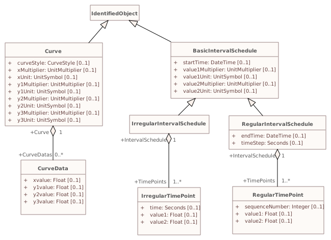
▶▦CurveSchedulei
CHANGED{7DCA2E11-355A-47f2-9EF8-BEAEBD619E5D}
Diagram notes
This diagram shows the common model for curves and time dependent schedules.Diagram metadata — changes
| Baseline | Destination | |
|---|---|---|
| ModifiedDate | 2019-03-05 09:53:37 | 2020-06-30 13:55:52 |
Diagram notes
This diagram shows the common model for curves and time dependent schedules.▤Metadata
| Baseline | Destination | |
|---|---|---|
| ModifiedDate | 2019-03-05 09:53:37 | 2020-06-30 13:55:52 |
▦Diagram
Baseline
Destination
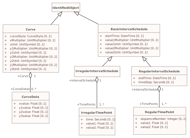
Connectors 1 reroutedhover a connector to outline the elements it joins
reroutedBasicIntervalSchedule – (not in this model)
▶▦FeederContainmenti
CHANGED{154626B0-2984-494a-B7D0-A92371728DC2}
Diagram notes
This diagram shows feeder containment.Diagram metadata — changes
| Baseline | Destination | |
|---|---|---|
| ModifiedDate | 2019-03-05 09:51:16 | 2020-06-16 14:29:42 |
Diagram notes
This diagram shows feeder containment.▤Metadata
| Baseline | Destination | |
|---|---|---|
| ModifiedDate | 2019-03-05 09:51:16 | 2020-06-16 14:29:42 |
Diagram 'FeederContainment' has no other changes. The shows its notes and every changed property.
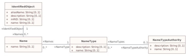
▶▦Namesi
CHANGED{E0451A91-94B6-4771-AA2F-2F1E5235FDE5}
Diagram notes
This diagram shows classes used to assign names to identified objects.Diagram metadata — changes
| Baseline | Destination | |
|---|---|---|
| ModifiedDate | 2014-01-30 10:13:09 | 2021-08-09 10:40:32 |
Diagram notes
This diagram shows classes used to assign names to identified objects.▤Metadata
| Baseline | Destination | |
|---|---|---|
| ModifiedDate | 2014-01-30 10:13:09 | 2021-08-09 10:40:32 |
▦Diagram
addedremovedchangedmoved or resized
Baseline
Destination
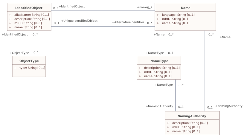
Connectors 4 added · 1 removed · 2 reroutedhover a connector to outline the elements it joins
addedName – IdentifiedObject
addedNamingAuthority – Name
addedNamingAuthority – NameType
addedObjectType – IdentifiedObject
removedNameType – NameTypeAuthority
reroutedName – IdentifiedObject
reroutedName – NameType
▶Wiresi
{6C99E9CA-2035-4035-B77F-9217E17D86F4}
Package notes
An extension to the Core and Topology package that models information on the electrical characteristics of Transmission and Distribution networks. This package is used by network applications such as State Estimation, Load Flow and Optimal Power Flow.Package metadata — changes
| Baseline | Destination | |
|---|---|---|
| no changes | ||
Tagged values — changes
| Baseline | Destination | |
|---|---|---|
| no changes | ||
Package notes
An extension to the Core and Topology package that models information on the electrical characteristics of Transmission and Distribution networks. This package is used by network applications such as State Estimation, Load Flow and Optimal Power Flow.Changed classes (23)
▶⚙ACLineSegmenti
CHANGED{625BD764-3907-4d65-8497-7FD09708BD8E}
Class notes
A wire or combination of wires, with consistent electrical characteristics, building a single electrical system, used to carry alternating current between points in the power system.
For symmetrical, transposed three phase lines, it is sufficient to use attributes of the line segment, which describe impedances and admittances for the entire length of the segment. Additionally impedances can be computed by using length and associated per length impedances.
The BaseVoltage at the two ends of ACLineSegments in a Line shall have the same BaseVoltage.nominalVoltage. However, boundary lines may have slightly different BaseVoltage.nominalVoltages and variation is allowed. Larger voltage difference in general requires use of an equivalent branch.Class metadata — changes
| Baseline | Destination | |
|---|---|---|
| no changes | ||
Tagged values — changes
| Baseline | Destination | |
|---|---|---|
| no changes | ||
Class notes
A wire or combination of wires, with consistent electrical characteristics, building a single electrical system, used to carry alternating current between points in the power system.
For symmetrical, transposed three phase lines, it is sufficient to use attributes of the line segment, which describe impedances and admittances for the entire length of the segment. Additionally impedances can be computed by using length and associated per length impedances.
The BaseVoltage at the two ends of ACLineSegments in a Line shall have the same BaseVoltage.nominalVoltage. However, boundary lines may have slightly different BaseVoltage.nominalVoltages and variation is allowed. Larger voltage difference in general requires use of an equivalent branch.⇄Links
CHANGEDAssociation{F29D4402-D392-434d-9E98-8C35F21BD856}
→
Source end — ACLineSegment
| Baseline | Destination | |
|---|---|---|
| RoleNote | The AC line segment defined by the wire spacing information | (empty) |
Target end — WireSpacingInfo
| Baseline | Destination | |
|---|---|---|
| RoleNote | The wire spacing information that applies to this AC line segment | (empty) |
▶⚙ACLineSegmentPhasei
CHANGED{84627F88-F666-4f07-890A-62622070CD0F}
Class notes
Represents a single wire of an alternating current line segment.Class metadata — changes
| Baseline | Destination | |
|---|---|---|
| no changes | ||
Tagged values — changes
| Baseline | Destination | |
|---|---|---|
| no changes | ||
Class notes
Represents a single wire of an alternating current line segment.⇄Links
CHANGEDAssociation{B5F55F86-9C19-4914-99C2-1ACBA0197A2E}
→
Source end — ACLineSegmentPhase
| Baseline | Destination | |
|---|---|---|
| RoleNote | AC line segment phase information associated with this wire information. | (empty) |
Target end — WireInfo
| Baseline | Destination | |
|---|---|---|
| RoleNote | Wire information contributing to this AC line segment phase information. | (empty) |
▶⚙Breakeri those of short circuit.
CHANGED{380D92AA-1D80-4e84-A8EE-843DACEB59DD}
Class notes (destination, redlined)
A mechanical switching device capable of making, carrying, and breaking currents under normal circuit conditions and also making, carrying for a specified time, and breaking currents under specified abnormal circuit conditions e.g.Class metadata — changes
| Baseline | Destination | |
|---|---|---|
| no changes | ||
Tagged values — changes
| Baseline | Destination | |
|---|---|---|
| no changes | ||
Class notes (destination, redlined)
A mechanical switching device capable of making, carrying, and breaking currents under normal circuit conditions and also making, carrying for a specified time, and breaking currents under specified abnormal circuit conditions e.g.Class 'Breaker' has no other changes. The shows its notes and every changed property.
▶⚙BusbarSectioni
CHANGED{0A63A81D-5142-4736-BD22-8C28BA32F233}
Class notes (destination, redlined)
A conductor, or group of conductors, with negligible impedance, that serve to connect other conducting equipment within a single substation.
Voltage measurements are typically obtained from voltage transformers that are connected to busbar sections. A bus bar section may have many physical terminals but for analysis is modelled with exactly one logical terminal.
The BusbarSection class is intended to represent physical parts of bus bars no matter how that bus bar is constructed.
Typically, BusbarSections and Junctions are represented by different symbols on diagrams.Class metadata — changes
| Baseline | Destination | |
|---|---|---|
| no changes | ||
Tagged values — changes
| Baseline | Destination | |
|---|---|---|
| no changes | ||
Class notes (destination, redlined)
A conductor, or group of conductors, with negligible impedance, that serve to connect other conducting equipment within a single substation.
Voltage measurements are typically obtained from voltage transformers that are connected to busbar sections. A bus bar section may have many physical terminals but for analysis is modelled with exactly one logical terminal.
The BusbarSection class is intended to represent physical parts of bus bars no matter how that bus bar is constructed.
Typically, BusbarSections and Junctions are represented by different symbols on diagrams.Class 'BusbarSection' has no other changes. The shows its notes and every changed property.
▶⚙Clampi
CHANGED{7B0758AF-6E8E-438e-BD69-A838A56F256D}
Class notes
A Clamp is a galvanic connection at a line segment where other equipment is connected. A Clamp does not cut the line segment.
A Clamp is ConductingEquipment and has one Terminal with an associated ConnectivityNode. Any other ConductingEquipment can be connected to the Clamp ConnectivityNode.Class metadata — changes
| Baseline | Destination | |
|---|---|---|
| no changes | ||
Tagged values — changes
| Baseline | Destination | |
|---|---|---|
| no changes | ||
Class notes
A Clamp is a galvanic connection at a line segment where other equipment is connected. A Clamp does not cut the line segment.
A Clamp is ConductingEquipment and has one Terminal with an associated ConnectivityNode. Any other ConductingEquipment can be connected to the Clamp ConnectivityNode.⇄Links
CHANGEDAssociation{74BBE709-CFEF-40a9-A120-33F704608576}
→
Source end — Clamp
| Baseline | Destination | |
|---|---|---|
| RoleNote | Clamp on which this action is taken. | (empty) |
Target end — JumperAction
| Baseline | Destination | |
|---|---|---|
| RoleNote | Action taken with this jumper. | (empty) |
CHANGEDAssociation{74C6F744-E53A-4fd0-BBA8-3531659CCC10}
→
Source end — Clamp
| Baseline | Destination | |
|---|---|---|
| RoleNote | The clamp that the clamp action is performed on | (empty) |
Target end — ClampAction
| Baseline | Destination | |
|---|---|---|
| RoleNote | The clamp action that is performed on the clamp | (empty) |
▶⚙EarthFaultCompensatori An earth fault compensator device modelled with a single terminal implies a second terminal solidly connected to ground. If two terminals are modelled, the ground is not assumed and normal connection rules apply.
CHANGED{99B51F43-C935-4382-AB8A-6352DAB082D4}
Class notes (destination, redlined)
A conducting equipment used to represent a connection to ground which is typically used to compensate earth faults.Class metadata — changes
| Baseline | Destination | |
|---|---|---|
| no changes | ||
Tagged values — changes
| Baseline | Destination | |
|---|---|---|
| no changes | ||
Class notes (destination, redlined)
A conducting equipment used to represent a connection to ground which is typically used to compensate earth faults.Class 'EarthFaultCompensator' has no other changes. The shows its notes and every changed property.
▶⚙EnergyConsumeri
CHANGED{BCEC7EE8-7294-4b50-8216-0286C31A035C}
Class notes
Generic user of energy - a point of consumption on the power system model.
EnergyConsumer.pfixed, .qfixed, .pfixedPct and .qfixedPct have meaning only if there is no LoadResponseCharacteristic associated with EnergyConsumer or if LoadResponseCharacteristic.exponentModel is set to False.Class metadata — changes
| Baseline | Destination | |
|---|---|---|
| no changes | ||
Tagged values — changes
| Baseline | Destination | |
|---|---|---|
| no changes | ||
Class notes
Generic user of energy - a point of consumption on the power system model.
EnergyConsumer.pfixed, .qfixed, .pfixedPct and .qfixedPct have meaning only if there is no LoadResponseCharacteristic associated with EnergyConsumer or if LoadResponseCharacteristic.exponentModel is set to False.⇄Links
CHANGEDAssociation{FED8229A-5B6E-4728-A961-4E85004FEA54}
BaselineEnergyConsumer role EnergyConsumer [0..1] → EnergyConsumerAction role EnergyConsumerAction [0..1]
→
DestinationEnergyConsumer role EnergyConsumer [0..1] → EnergyConsumerAction role EnergyConsumerAction [0..1]
Source end — EnergyConsumer
| Baseline | Destination | |
|---|---|---|
| RoleNote | The energy consumer that the energy consumer action is performed on | (empty) |
Target end — EnergyConsumerAction
| Baseline | Destination | |
|---|---|---|
| RoleNote | The energy consumer action that is performed on the energy consumer | (empty) |
▶⚙ExternalNetworkInjectioniit is used for IEC 60909 calculations.
CHANGED{B7E110A4-CE7A-4414-9477-4310D44B43D0}
Class notes (destination, redlined)
This class represents the external network and Class metadata — changes
| Baseline | Destination | |
|---|---|---|
| no changes | ||
Tagged values — changes
| Baseline | Destination | |
|---|---|---|
| no changes | ||
Class notes (destination, redlined)
This class represents the external network and ≡Attributes
| Attribute | Baseline | Destination | Notes (destination, redlined) | ||||||||||||
|---|---|---|---|---|---|---|---|---|---|---|---|---|---|---|---|
| minR0ToX0Ratioi{BCD7177E-8D88-4797-949C-3068CE234417}show details | Float [0..1] | Float [0..1] | Indicates whether initial symmetrical short-circuit current and power have been calculated according to IEC (Ik"). Used for short circuit data exchange according to IEC | ||||||||||||
Attribute notes (destination, redlined) Indicates whether initial symmetrical short-circuit current and power have been calculated according to IEC (Ik"). Used for short circuit data exchange according to IEC Attribute metadata — changes
Tagged values — changes
| |||||||||||||||
▶⚙JunctioniA point where one or more conducting equipments are connected with zero resistance. A point where one or more conducting equipments are connected with zero resistance.
The Junction class is intended to provide a place to associate additional information to a connectivity node which connects two or more equipment terminals. Examples include a tee-point or the connection point between two switches.
Typically, BusbarSections and Junctions are represented by different symbols on diagrams.
CHANGED{BE90EE60-8212-44ec-9F4D-775719E80216}
Class notes (destination, redlined)
Class metadata — changes
| Baseline | Destination | |
|---|---|---|
| no changes | ||
Tagged values — changes
| Baseline | Destination | |
|---|---|---|
| no changes | ||
Class notes (destination, redlined)
Class 'Junction' has no other changes. The shows its notes and every changed property.
▶⚙PhaseTapChangerAsymmetricali The angle between the in-phase and out-of-phase windings is named the winding connection angle. The phase shift depends on both the difference voltage magnitude and the winding connection angle.
CHANGED{4161A809-7542-4c92-A7D0-99AE5682E89C}
Class notes (destination, redlined)
Describes the tap model for an asymmetrical phase shifting transformer in which the difference voltage vector adds to the in-phase winding. The out-of-phase winding is the transformer end where the tap changer is located.Class metadata — changes
| Baseline | Destination | |
|---|---|---|
| no changes | ||
Tagged values — changes
| Baseline | Destination | |
|---|---|---|
| no changes | ||
Class notes (destination, redlined)
Describes the tap model for an asymmetrical phase shifting transformer in which the difference voltage vector adds to the in-phase winding. The out-of-phase winding is the transformer end where the tap changer is located.≡Attributes
| Attribute | Baseline | Destination | Notes (destination, redlined) | ||||||||||||
|---|---|---|---|---|---|---|---|---|---|---|---|---|---|---|---|
| windingConnectionAnglei{73F12408-9962-4614-8F76-9276D859E042}show details | AngleDegrees [0..1] | AngleDegrees [0..1] | The phase angle between the in-phase winding and the out-of -phase winding used for creating phase shift. The out-of-phase winding produces what is known as the difference voltage. Setting this angle to 90 degrees is not the same as a symmetrical transformer. The attribute can only be multiples of 30 degrees. | ||||||||||||
Attribute notes (destination, redlined) The phase angle between the in-phase winding and the out-of -phase winding used for creating phase shift. The out-of-phase winding produces what is known as the difference voltage. Setting this angle to 90 degrees is not the same as a symmetrical transformer. The attribute can only be multiples of 30 degrees.Attribute metadata — changes
Tagged values — changes
| |||||||||||||||
▶⚙PowerTransformeri A power transformer typically has two terminals, but may have one (grounding), three or more terminals.
The inherited association ConductingEquipment.BaseVoltage should not be used. The association from TransformerEnd to BaseVoltage should be used instead.
CHANGED{3D50627C-324C-4e9d-AB5C-592E0A1E0AFE}
Class notes (destination, redlined)
An electrical device consisting of two or more coupled windings, with or without a magnetic core, for introducing mutual coupling between electric circuits. Transformers can be used to control voltage and phase shift (active power flow).
A power transformer may be composed of separate transformer tanks that need not be identical.
A power transformer can be modelled with or without tanks and is intended for use in both balanced and unbalanced representations.Class metadata — changes
| Baseline | Destination | |
|---|---|---|
| no changes | ||
Tagged values — changes
| Baseline | Destination | |
|---|---|---|
| no changes | ||
Class notes (destination, redlined)
An electrical device consisting of two or more coupled windings, with or without a magnetic core, for introducing mutual coupling between electric circuits. Transformers can be used to control voltage and phase shift (active power flow).
A power transformer may be composed of separate transformer tanks that need not be identical.
A power transformer can be modelled with or without tanks and is intended for use in both balanced and unbalanced representations.Class 'PowerTransformer' has no other changes. The shows its notes and every changed property.
▶⚙RegulatingControli- to 4 kV compared to the on shore station. Thus in normal operation the tap changer on the on shore station is operated with a target set point, which is in the lower parts of the dead band.
The attributes minAllowedTargetValue and maxAllowedTargetValue are not related to the attribute targetDeadband and thus they are not treated as an alternative of the targetDeadband. They are needed due to limitations in the local substation controller. The attribute targetDeadband is used to prevent the power flow from move the tap position in circles (hunting) that is to be used regardless of the attributes minAllowedTargetValue and maxAllowedTargetValue.
CHANGED{8C28B28D-4735-4033-9F33-7D86F6819922}
Class notes (destination, redlined)
Specifies a set of equipment that works together to control a power system quantity such as voltage or flow.
Remote bus voltage control is possible by specifying the controlled terminal located at some place remote from the controlling equipment.
The specified terminal shall be associated with the connectivity node of the controlled point. The most specific subtype of RegulatingControl shall be used in case such equipment participate in the control, e.g. TapChangerControl for tap changers.
For flow control, load sign convention is used, i.e. positive sign means flow out from a TopologicalNode (bus) into the conducting equipment.
The attribute minAllowedTargetValue and maxAllowedTargetValue are required in the following cases:
- For a power generating module operated in power factor control mode to specify maximum and minimum power factor values;
- Whenever it is necessary to have an off center target voltage for the tap changer regulator. For instance, due to long cables to off shore wind farms and the need to have a simpler setup at the off shore transformer platform, the voltage is controlled from the land at the connection point for the off shore wind farm. Since there usually is a voltage rise along the cable, there is typical and overvoltage of up 3Class metadata — changes
| Baseline | Destination | |
|---|---|---|
| no changes | ||
Tagged values — changes
| Baseline | Destination | |
|---|---|---|
| no changes | ||
Class notes (destination, redlined)
Specifies a set of equipment that works together to control a power system quantity such as voltage or flow.
Remote bus voltage control is possible by specifying the controlled terminal located at some place remote from the controlling equipment.
The specified terminal shall be associated with the connectivity node of the controlled point. The most specific subtype of RegulatingControl shall be used in case such equipment participate in the control, e.g. TapChangerControl for tap changers.
For flow control, load sign convention is used, i.e. positive sign means flow out from a TopologicalNode (bus) into the conducting equipment.
The attribute minAllowedTargetValue and maxAllowedTargetValue are required in the following cases:
- For a power generating module operated in power factor control mode to specify maximum and minimum power factor values;
- Whenever it is necessary to have an off center target voltage for the tap changer regulator. For instance, due to long cables to off shore wind farms and the need to have a simpler setup at the off shore transformer platform, the voltage is controlled from the land at the connection point for the off shore wind farm. Since there usually is a voltage rise along the cable, there is typical and overvoltage of up 3Class 'RegulatingControl' has no other changes. The shows its notes and every changed property.
▶⚙SeriesCompensatori
CHANGED{5B656059-8C65-455e-9E02-5A14C2631D6A}
Class notes
A Series Compensator is a series capacitor or reactor or an AC transmission line without charging susceptance. It is a two terminal device.Class metadata — changes
| Baseline | Destination | |
|---|---|---|
| no changes | ||
Tagged values — changes
| Baseline | Destination | |
|---|---|---|
| no changes | ||
Class notes
A Series Compensator is a series capacitor or reactor or an AC transmission line without charging susceptance. It is a two terminal device.≡Attributes
| Attribute | Baseline | Destination | Notes (destination, redlined) | ||||||||||||
|---|---|---|---|---|---|---|---|---|---|---|---|---|---|---|---|
| varistorVoltageThresholdi{5E30BCEC-E8EB-4b1d-9AE5-E44FF6B0FFDE}show details | Voltage [0..1] | Voltage [0..1] | The | ||||||||||||
Attribute notes (destination, redlined) The Attribute metadata — changes
Tagged values — changes
| |||||||||||||||
▶⚙ShuntCompensatori
CHANGED{92B30569-5ED0-4fc0-B796-984D9BF75453}
Class notes
A shunt capacitor or reactor or switchable bank of shunt capacitors or reactors. A section of a shunt compensator is an individual capacitor or reactor. A negative value for bPerSection indicates that the compensator is a reactor. ShuntCompensator is a single terminal device. Ground is implied.Class metadata — changes
| Baseline | Destination | |
|---|---|---|
| no changes | ||
Tagged values — changes
| Baseline | Destination | |
|---|---|---|
| no changes | ||
Class notes
A shunt capacitor or reactor or switchable bank of shunt capacitors or reactors. A section of a shunt compensator is an individual capacitor or reactor. A negative value for bPerSection indicates that the compensator is a reactor. ShuntCompensator is a single terminal device. Ground is implied.≡Attributes
| Attribute | Baseline | Destination | Notes (destination, redlined) | |||||||||||||||||||||||||||||||||||||||||||||
|---|---|---|---|---|---|---|---|---|---|---|---|---|---|---|---|---|---|---|---|---|---|---|---|---|---|---|---|---|---|---|---|---|---|---|---|---|---|---|---|---|---|---|---|---|---|---|---|---|
| sectionsi{092847A7-BC7D-4682-BA72-84E03733C148}show details | Float [0..1] | Float [0..1] | Shunt compensator sections in use. Starting value for steady state solution. The attribute shall be a positive value or zero. Non integer values are allowed to support continuous variables. The reasons for continuous value are to support study cases where no discrete shunt compensators has yet been designed, a solutions where a narrow voltage band force the sections to oscillate or accommodate for a continuous solution as input. For LinearShuntConpensator the value shall be between zero and ShuntCompensator.maximumSections. At value zero the shunt compensator conductance and admittance is zero. Linear interpolation of conductance and admittance between the previous and next integer section is applied in case of non-integer values. For NonlinearShuntCompensator(-s) shall only be set to one of the NonlinearShuntCompenstorPoint.sectionNumber. There is no interpolation between NonlinearShuntCompenstorPoint(-s). | |||||||||||||||||||||||||||||||||||||||||||||
Attribute notes (destination, redlined) Shunt compensator sections in use. Starting value for steady state solution. The attribute shall be a positive value or zero. Non integer values are allowed to support continuous variables. The reasons for continuous value are to support study cases where no discrete shunt compensators has yet been designed, a solutions where a narrow voltage band force the sections to oscillate or accommodate for a continuous solution as input.
For LinearShuntConpensator the value shall be between zero and ShuntCompensator.maximumSections. At value zero the shunt compensator conductance and admittance is zero. Linear interpolation of conductance and admittance between the previous and next integer section is applied in case of non-integer values.
For NonlinearShuntCompensator(-s) shall only be set to one of the NonlinearShuntCompenstorPoint.sectionNumber. There is no interpolation between NonlinearShuntCompenstorPoint(-s).Attribute metadata — changes
Tagged values — changes
| ||||||||||||||||||||||||||||||||||||||||||||||||
| switchOnCounti{29F942BE-335A-4233-88AA-8F66D2BA8E58}show details | Integer [0..1] | removed from model | ||||||||||||||||||||||||||||||||||||||||||||||
Attribute notes (baseline) The switch on count since the capacitor count was last reset or initialized.Attribute metadata — changes
Tagged values — changes
| ||||||||||||||||||||||||||||||||||||||||||||||||
| switchOnDatei{8D542910-E6DF-4244-A561-DC898FCF6924}show details | DateTime [0..1] | removed from model | ||||||||||||||||||||||||||||||||||||||||||||||
Attribute notes (baseline) The date and time when the capacitor bank was last switched on.Attribute metadata — changes
Tagged values — changes
| ||||||||||||||||||||||||||||||||||||||||||||||||
⇄Links
CHANGEDAssociation{9AE30218-76B9-40f7-A698-BEA89FA25113}
BaselineShuntCompensator role ShuntCompensator [0..1] → ShuntCompensatorAction role ShuntCompensatorAction [0..1]
→
DestinationShuntCompensator role ShuntCompensator [0..1] → ShuntCompensatorAction role ShuntCompensatorAction [0..1]
Source end — ShuntCompensator
| Baseline | Destination | |
|---|---|---|
| RoleNote | The shunt compensator that the shunt compensator action is performed on | (empty) |
Target end — ShuntCompensatorAction
| Baseline | Destination | |
|---|---|---|
| RoleNote | The shunt compensator action that is performed on the shunt compensator | (empty) |
▶⚙SinglePhaseKind«enumeration»isinglephase identifiers used to designate the specific phase identifiersof conducting equipment modelled as individual unbalanced phases.
Allows designation of singlespecific phases for both transmission and distribution equipment, circuits and loads.
CHANGED{0AD52D65-4270-45c1-9AF4-29C53A398AE3}
Class notes (destination, redlined)
Enumeration of Class metadata — changes
| Baseline | Destination | |
|---|---|---|
| no changes | ||
Tagged values — changes
| Baseline | Destination | |
|---|---|---|
| no changes | ||
Class notes (destination, redlined)
Enumeration of Class 'SinglePhaseKind' has no other changes. The shows its notes and every changed property.
▶⚙StaticVarCompensatori The SVC characteristic slope defines the proportion. If the voltage at the controlled bus is equal to the voltage setpoint, the SVC MVar output is zero.
CHANGED{B540EF99-8CE4-4da6-9E4D-D22E867F8BAE}
Class notes (destination, redlined)
A facility for providing variable and controllable shunt reactive power. The SVC typically consists of a stepdown transformer, filter, thyristor-controlled reactor, and thyristor-switched capacitor arms.
The SVC may operate in fixed MVar output mode or in voltage control mode. When in voltage control mode, the output of the SVC will be proportional to the deviation of voltage at the controlled bus from the voltage setpoint.Class metadata — changes
| Baseline | Destination | |
|---|---|---|
| no changes | ||
Tagged values — changes
| Baseline | Destination | |
|---|---|---|
| no changes | ||
Class notes (destination, redlined)
A facility for providing variable and controllable shunt reactive power. The SVC typically consists of a stepdown transformer, filter, thyristor-controlled reactor, and thyristor-switched capacitor arms.
The SVC may operate in fixed MVar output mode or in voltage control mode. When in voltage control mode, the output of the SVC will be proportional to the deviation of voltage at the controlled bus from the voltage setpoint.≡Attributes
| Attribute | Baseline | Destination | Notes (destination, redlined) | |||||||||||||||
|---|---|---|---|---|---|---|---|---|---|---|---|---|---|---|---|---|---|---|
| capacitiveRatingi{E35F733F-7F1A-4124-8539-BE6FEE250CCD}show details | Reactance [0..1] | Reactance [0..1] | Capacitive reactance at maximum capacitive reactive power. | |||||||||||||||
Attribute notes (destination, redlined) Capacitive reactance at maximum capacitive reactive power.Attribute metadata — changes
Tagged values — changes
| ||||||||||||||||||
| inductiveRatingi{3F4C093D-2CC5-4ee5-A225-31D4B7AFD3AC}show details | Reactance [0..1] | Reactance [0..1] | Inductive reactance at maximum inductive reactive power. | |||||||||||||||
Attribute notes (destination, redlined) Inductive reactance at maximum inductive reactive power.Attribute metadata — changes
Tagged values — changes
| ||||||||||||||||||
| sVCControlModeimetadata changed - hovermetadata changedrenamed from «deprecated» sVCControlMode{5D29151B-3D23-4964-BE66-3C58A2D84411}show details | SVCControlMode [0..1] | SVCControlMode [0..1] | SVC control mode. | |||||||||||||||
Attribute notes SVC control mode.Attribute metadata — changes
Tagged values — changes
| ||||||||||||||||||
| voltageSetPointimetadata changed - hovermetadata changedrenamed from «deprecated» voltageSetPoint{170589DF-9B85-487a-BC91-4BC8ECB1D88C}show details | Voltage [0..1] | Voltage [0..1] | The reactive power output of the SVC is proportional to the difference between the voltage at the regulated bus and the voltage setpoint. When the regulated bus voltage is equal to the voltage setpoint, the reactive power output is zero. | |||||||||||||||
Attribute notes The reactive power output of the SVC is proportional to the difference between the voltage at the regulated bus and the voltage setpoint. When the regulated bus voltage is equal to the voltage setpoint, the reactive power output is zero.Attribute metadata — changes
Tagged values — changes
| ||||||||||||||||||
▶⚙SVCControlMode«enumeration»i
CHANGED{269933B9-3FD0-433d-B360-86FF6CDCDDC8}
Class notes
Static VAr Compensator control mode.Class metadata — changes
| Baseline | Destination | |
|---|---|---|
| Stereotype | enumeration, deprecated | enumeration |
Tagged values — changes
| Baseline | Destination | |
|---|---|---|
| no changes | ||
Class notes
Static VAr Compensator control mode.▤Metadata
| Baseline | Destination | |
|---|---|---|
| Stereotype | enumeration, deprecated | enumeration |
≡Attributes
| Attribute | Baseline | Destination | Notes (destination, redlined) | ||||||||||||
|---|---|---|---|---|---|---|---|---|---|---|---|---|---|---|---|
| reactivePowerimetadata changed - hovermetadata changed{1090360B-E8A3-4e71-B538-629F660CB01B}show details | [1..1] | [1..1] | Reactive power control. | ||||||||||||
Attribute notes Reactive power control.Attribute metadata — changes
Tagged values — changes
| |||||||||||||||
▶⚙Switchi
CHANGED{ACE2DDBB-536E-489a-A3A8-22589256302D}
Class notes
A generic device designed to close, or open, or both, one or more electric circuits. All switches are two terminal devices including grounding switches. The ACDCTerminal.connected at the two sides of the switch shall not be considered for assessing switch connectivity, i.e. only Switch.open, .normalOpen and .locked are relevant.Class metadata — changes
| Baseline | Destination | |
|---|---|---|
| no changes | ||
Tagged values — changes
| Baseline | Destination | |
|---|---|---|
| no changes | ||
Class notes
A generic device designed to close, or open, or both, one or more electric circuits. All switches are two terminal devices including grounding switches. The ACDCTerminal.connected at the two sides of the switch shall not be considered for assessing switch connectivity, i.e. only Switch.open, .normalOpen and .locked are relevant.≡Attributes
| Attribute | Baseline | Destination | Notes (destination, redlined) | |||||||||||||||||||||||||||||||||||||||||||||
|---|---|---|---|---|---|---|---|---|---|---|---|---|---|---|---|---|---|---|---|---|---|---|---|---|---|---|---|---|---|---|---|---|---|---|---|---|---|---|---|---|---|---|---|---|---|---|---|---|
| switchOnCounti{0FA70685-F30F-4d40-9CA6-65C5C7AC0543}show details | Integer [0..1] | removed from model | ||||||||||||||||||||||||||||||||||||||||||||||
Attribute notes (baseline) The switch on count since the switch was last reset or initialized.Attribute metadata — changes
Tagged values — changes
| ||||||||||||||||||||||||||||||||||||||||||||||||
| switchOnDatei{49CABBEB-6179-48ca-A1D3-4D45B67C7058}show details | DateTime [0..1] | removed from model | ||||||||||||||||||||||||||||||||||||||||||||||
Attribute notes (baseline) The date and time when the switch was last switched on.Attribute metadata — changes
Tagged values — changes
| ||||||||||||||||||||||||||||||||||||||||||||||||
▶⚙SwitchSchedulei If RegularTimePoint.value1 is 0, the switch is open. If 1, the switch is closed.
CHANGED{3C7AD112-5779-4f2a-8A87-ABB7FBA99EBF}
Class notes (destination, redlined)
A schedule of switch positions.Class metadata — changes
| Baseline | Destination | |
|---|---|---|
| no changes | ||
Tagged values — changes
| Baseline | Destination | |
|---|---|---|
| no changes | ||
Class notes (destination, redlined)
A schedule of switch positions.Class 'SwitchSchedule' has no other changes. The shows its notes and every changed property.
▶⚙SynchronousMachinei
CHANGED{7862E21E-F054-4a33-949F-04B8B4690D49}
Class notes
An electromechanical device that operates with shaft rotating synchronously with the network. It is a single machine operating either as a generator or synchronous condenser or pump.Class metadata — changes
| Baseline | Destination | |
|---|---|---|
| no changes | ||
Tagged values — changes
| Baseline | Destination | |
|---|---|---|
| no changes | ||
Class notes
An electromechanical device that operates with shaft rotating synchronously with the network. It is a single machine operating either as a generator or synchronous condenser or pump.≡Attributes
| Attribute | Baseline | Destination | Notes (destination, redlined) | ||||||||||||
|---|---|---|---|---|---|---|---|---|---|---|---|---|---|---|---|
| mui{848A6DD0-9E82-42fa-B11B-8532CB3D9AA3}show details | Float [0..1] | Float [0..1] | Factor to calculate the breaking current ( | ||||||||||||
Attribute notes (destination, redlined) Factor to calculate the breaking current (Attribute metadata — changes
Tagged values — changes
| |||||||||||||||
| qPercenti{3CBD29B9-1D15-4816-8720-F72FF7CE0C5D}show details | PerCent [0..1] | PerCent [0..1] | Part of the coordinated reactive control that comes from this machine. The attribute is used as a participation factor not necessarily summing up to 100 % for the participating devices in the control. | ||||||||||||
Attribute notes (destination, redlined) Part of the coordinated reactive control that comes from this machine. The attribute is used as a participation factor not necessarily summing up to 100 % for the participating devices in the control.Attribute metadata — changes
Tagged values — changes
| |||||||||||||||
▶⚙TapChangeri
CHANGED{F43099C0-90EA-47f1-B038-EDE831744C07}
Class notes
Mechanism for changing transformer winding tap positions.Class metadata — changes
| Baseline | Destination | |
|---|---|---|
| no changes | ||
Tagged values — changes
| Baseline | Destination | |
|---|---|---|
| no changes | ||
Class notes
Mechanism for changing transformer winding tap positions.≡Attributes
| Attribute | Baseline | Destination | Notes (destination, redlined) | ||||||||||||
|---|---|---|---|---|---|---|---|---|---|---|---|---|---|---|---|
| neutralStepi{AEF6801E-342A-4a1f-ADC6-C7DAFFED61BC}show details | Integer [0..1] | Integer [0..1] | The neutral tap step position for this winding.
The attribute shall be equal to or greater than lowStep and equal or less than highStep.
It is the step position where the voltage is neutralU when the other terminals of the transformer are at the ratedU. | ||||||||||||
Attribute notes (destination, redlined) The neutral tap step position for this winding.
The attribute shall be equal to or greater than lowStep and equal or less than highStep.
It is the step position where the voltage is neutralU when the other terminals of the transformer are at the ratedU.Attribute metadata — changes
Tagged values — changes
| |||||||||||||||
▶⚙TapChangerTablePointi
CHANGED{199B695F-644C-4cbf-AB67-76AB51EE5078}
Class notes
Describes each tap step in the tabular curve.Class metadata — changes
| Baseline | Destination | |
|---|---|---|
| no changes | ||
Tagged values — changes
| Baseline | Destination | |
|---|---|---|
| no changes | ||
Class notes
Describes each tap step in the tabular curve.≡Attributes
| Attribute | Baseline | Destination | Notes (destination, redlined) | ||||||||||||
|---|---|---|---|---|---|---|---|---|---|---|---|---|---|---|---|
| bi{EA68668F-E3EE-4702-978C-26D6BCED0B86}show details | PerCent [0..1] | PerCent [0..1] | The magnetizing branch susceptance deviation as a percentage of nominal value. The actual susceptance is calculated as follows:
calculated magnetizing susceptance = b(nominal) * (1 + b(from this class)/100). The b(nominal) is defined as the static magnetizing susceptance on the associated power transformer end or ends. | ||||||||||||
Attribute notes (destination, redlined) The magnetizing branch susceptance deviation as a percentage of nominal value. The actual susceptance is calculated as follows:
calculated magnetizing susceptance = b(nominal) * (1 + b(from this class)/100). The b(nominal) is defined as the static magnetizing susceptance on the associated power transformer end or ends.Attribute metadata — changes
Tagged values — changes
| |||||||||||||||
| gi{F33BB85C-0624-4ff6-BA15-DBDA563BB4FB}show details | PerCent [0..1] | PerCent [0..1] | The magnetizing branch conductance deviation as a percentage of nominal value. The actual conductance is calculated as follows:
calculated magnetizing conductance = g(nominal) * (1 + g(from this class)/100). The g(nominal) is defined as the static magnetizing conductance on the associated power transformer end or ends. | ||||||||||||
Attribute notes (destination, redlined) The magnetizing branch conductance deviation as a percentage of nominal value. The actual conductance is calculated as follows:
calculated magnetizing conductance = g(nominal) * (1 + g(from this class)/100). The g(nominal) is defined as the static magnetizing conductance on the associated power transformer end or ends.Attribute metadata — changes
Tagged values — changes
| |||||||||||||||
| ri{81B79598-EB65-43c7-A0E5-B982F1EDF158}show details | PerCent [0..1] | PerCent [0..1] | The resistance deviation as a percentage of nominal value. The actual reactance is calculated as follows:
calculated resistance = r(nominal) * (1 + r(from this class)/100). | ||||||||||||
Attribute notes (destination, redlined) The resistance deviation as a percentage of nominal value. The actual reactance is calculated as follows:
calculated resistance = r(nominal) * (1 + r(from this class)/100).Attribute metadata — changes
Tagged values — changes
| |||||||||||||||
| xi{55B6B5C3-6A91-4136-936A-8AF71058D544}show details | PerCent [0..1] | PerCent [0..1] | The series reactance deviation as a percentage of nominal value. The actual reactance is calculated as follows:
calculated reactance = x(nominal) * (1 + x(from this class)/100). | ||||||||||||
Attribute notes (destination, redlined) The series reactance deviation as a percentage of nominal value. The actual reactance is calculated as follows:
calculated reactance = x(nominal) * (1 + x(from this class)/100).Attribute metadata — changes
Tagged values — changes
| |||||||||||||||
▶⚙TransformerEndi In earlier CIM versions, the TransformerWinding class served a similar purpose, but this class is more flexible because it associates to terminal but is not a specialization of ConductingEquipment.
CHANGED{6E6AF445-8CD5-434b-8E74-08970A4E6D95}
Class notes (destination, redlined)
A conducting connection point of a power transformer. It corresponds to a physical transformer winding terminal.Class metadata — changes
| Baseline | Destination | |
|---|---|---|
| no changes | ||
Tagged values — changes
| Baseline | Destination | |
|---|---|---|
| no changes | ||
Class notes (destination, redlined)
A conducting connection point of a power transformer. It corresponds to a physical transformer winding terminal.≡Attributes
| Attribute | Baseline | Destination | Notes (destination, redlined) | ||||||||||||
|---|---|---|---|---|---|---|---|---|---|---|---|---|---|---|---|
| endNumberi{6822B571-71B1-4ce5-AEFB-1B41C19076AF}show details | Integer [0..1] | Integer [0..1] | Number for this transformer end, corresponding to the end's order in the power transformer vector group or phase angle clock number. | ||||||||||||
Attribute notes (destination, redlined) Number for this transformer end, corresponding to the end's order in the power transformer vector group or phase angle clock number.Attribute metadata — changes
Tagged values — changes
| |||||||||||||||
⇄Links
CHANGEDAssociation{DEF1E6AE-B7B9-43bf-9A91-E4BFC453DC4D}
→
Source end — TransformerEnds
| Baseline | Destination | |
|---|---|---|
| RoleNote | Transformer ends at the base voltage. This is essential for PU calculation. | Transformer ends at the base voltage. |
Target end — BaseVoltage
| Baseline | Destination | |
|---|---|---|
| RoleNote | Base voltage of the transformer end. This is essential for PU calculation. | Base voltage of the transformer end. |
Changed diagrams (7)
▶▦Datatypesi
CHANGED{7F25DAE7-CB22-4224-AFEB-7F0BD8317D69}
Diagram notes
This diagram shows the data types specific to the Wires package.Diagram metadata — changes
| Baseline | Destination | |
|---|---|---|
| no changes | ||
Diagram notes
This diagram shows the data types specific to the Wires package.▦Diagram
changed
Baseline
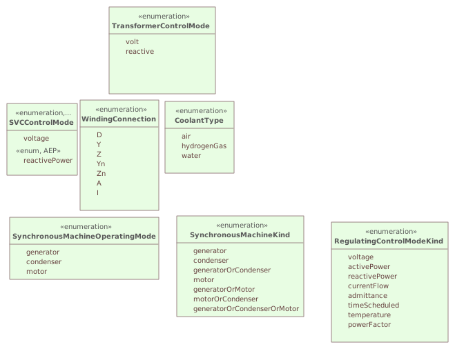
Destination
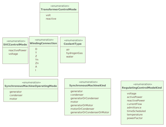
▶▦InheritanceHierarchyi
CHANGED{D2B8C355-D454-4084-9966-12E8D7FF6875}
Diagram notes
This diagram describes inheritance between classes in and related to the Wires package.Diagram metadata — changes
| Baseline | Destination | |
|---|---|---|
| no changes | ||
Diagram notes
This diagram describes inheritance between classes in and related to the Wires package.▦Diagram
changed
Baseline
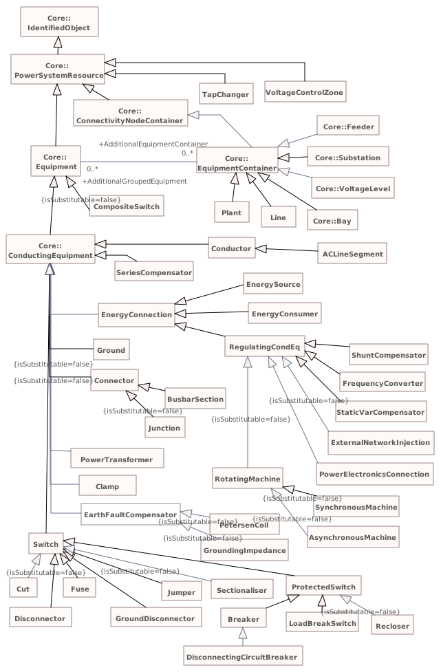
Destination
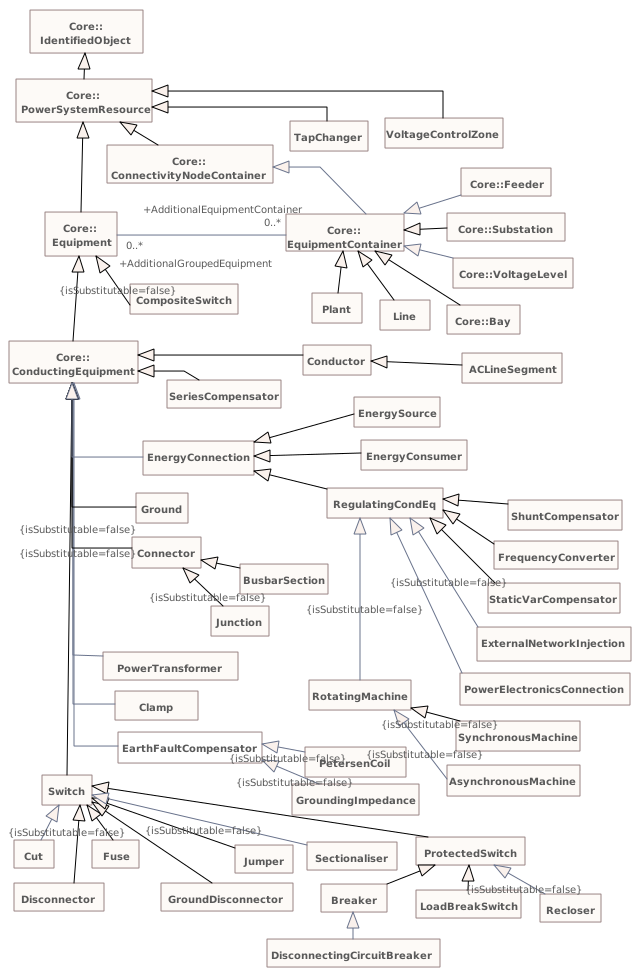
▶▦NamingHierarchyPart2i
CHANGED{3A72A435-5BA5-4809-A5DC-560573D58582}
Diagram notes
The diagram shows the lower part of the naming hierarchy. It shows how the Equipment class is further specialized into many subtypes that are all contained by subclasses of the EquipmentContainer. For the subclasses of equipment container refer to part 1 of the diagram.Diagram metadata — changes
| Baseline | Destination | |
|---|---|---|
| no changes | ||
Diagram notes
The diagram shows the lower part of the naming hierarchy. It shows how the Equipment class is further specialized into many subtypes that are all contained by subclasses of the EquipmentContainer. For the subclasses of equipment container refer to part 1 of the diagram.▦Diagram
changed
Baseline
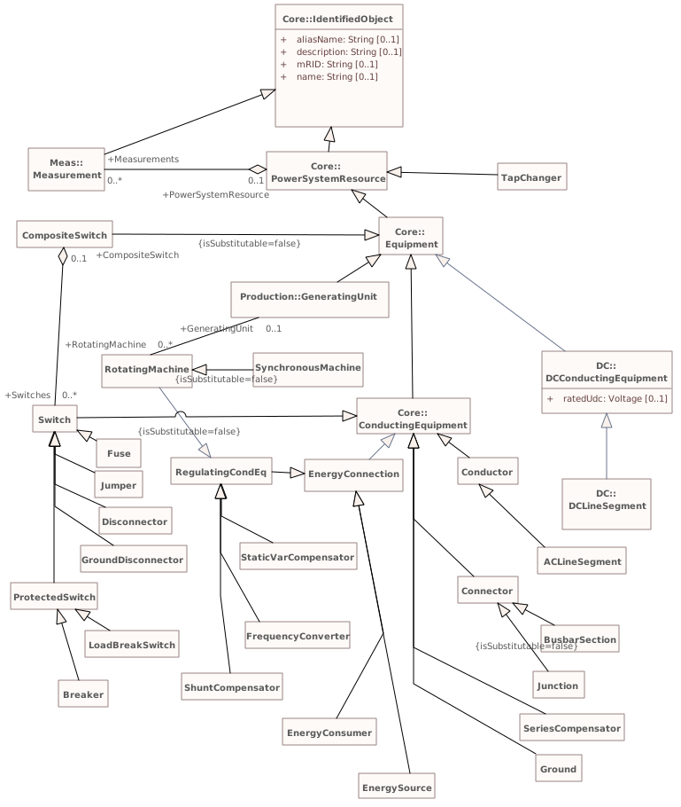
Destination
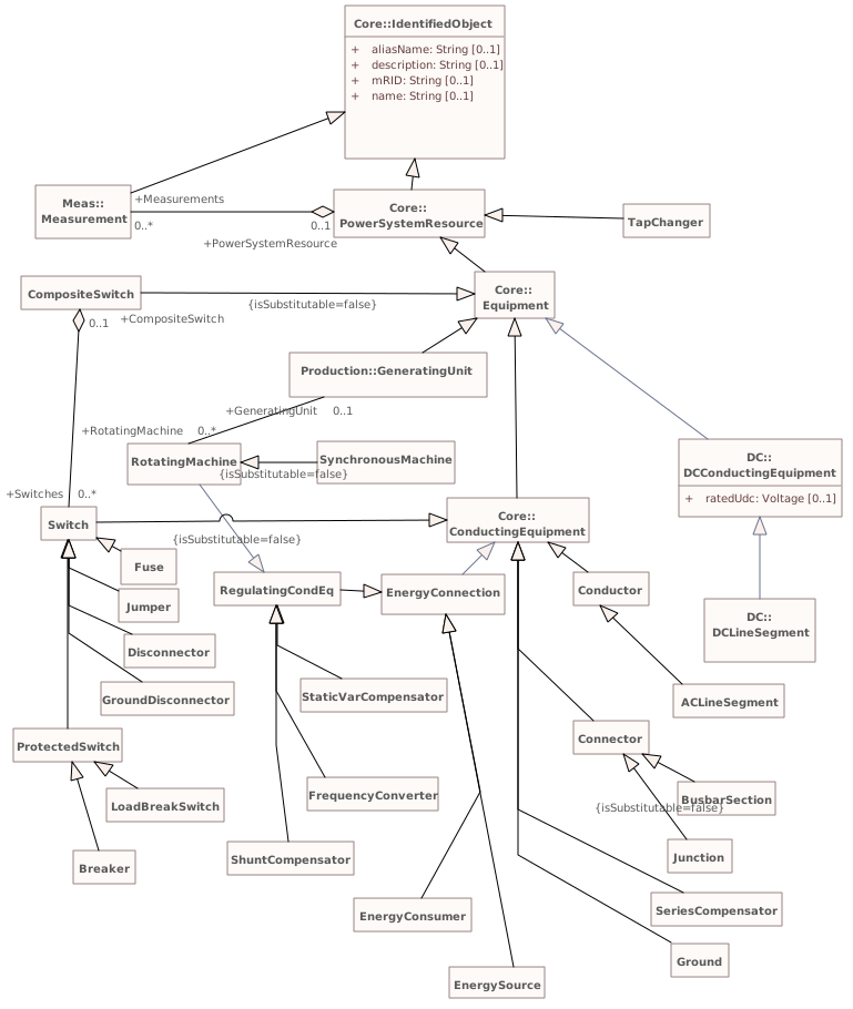
▶▦RegulatingEquipmenti
CHANGED{F857266A-1599-4d8c-8AC8-29B416B63FA2}
Diagram notes
The diagram shows all classes related to equipment regulation and reactive power compensation.Diagram metadata — changes
| Baseline | Destination | |
|---|---|---|
| ModifiedDate | 2020-07-01 21:30:24 | 2019-11-05 06:52:43 |
Diagram notes
The diagram shows all classes related to equipment regulation and reactive power compensation.▤Metadata
| Baseline | Destination | |
|---|---|---|
| ModifiedDate | 2020-07-01 21:30:24 | 2019-11-05 06:52:43 |
▦Diagram
changed
Baseline
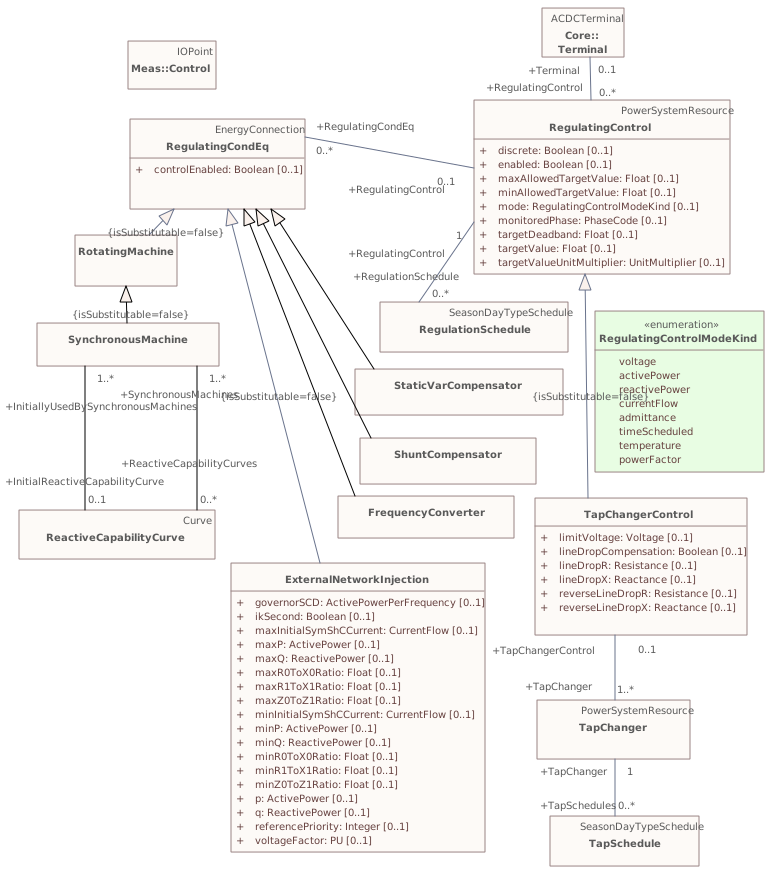
Destination
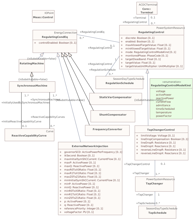
▶▦ShuntCompensatori
CHANGED{3CAA0009-F451-4e6d-BEDE-2AD7E67D3C35}
Diagram notes
Shows shunt compensator inheritance structure.Diagram metadata — changes
| Baseline | Destination | |
|---|---|---|
| ModifiedDate | 2019-03-05 10:23:07 | 2021-08-06 12:44:19 |
Diagram notes
Shows shunt compensator inheritance structure.▤Metadata
| Baseline | Destination | |
|---|---|---|
| ModifiedDate | 2019-03-05 10:23:07 | 2021-08-06 12:44:19 |
▦Diagram
changedmoved or resized
Baseline
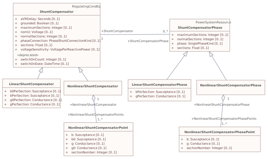
Destination
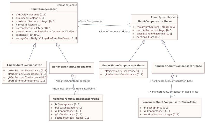
▶▦SwitchingEquipmenti
CHANGED{252E3FAB-DD51-437d-886F-5F699257FD4C}
Diagram notes
Shows switching equipment inheritance structure.Diagram metadata — changes
| Baseline | Destination | |
|---|---|---|
| ModifiedDate | 2019-09-20 07:47:43 | 2021-08-06 12:44:48 |
Diagram notes
Shows switching equipment inheritance structure.▤Metadata
| Baseline | Destination | |
|---|---|---|
| ModifiedDate | 2019-09-20 07:47:43 | 2021-08-06 12:44:48 |
▦Diagram
changed
Baseline
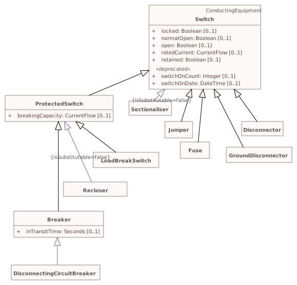
Destination
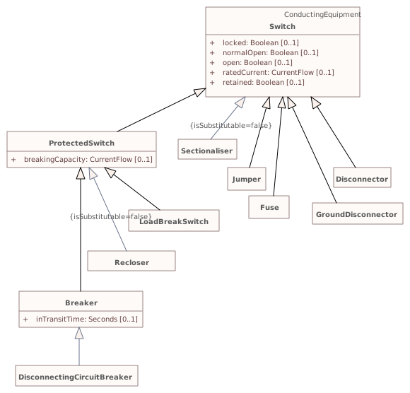
▶▦TapChangeri
CHANGED{E6AB0688-D20A-4495-802A-28F4BC2E446D}
Diagram notes
This diagram shows all classes related to the transformer tap model.Diagram metadata — changes
| Baseline | Destination | |
|---|---|---|
| ModifiedDate | 2020-07-01 21:30:24 | 2019-03-05 10:24:20 |
Diagram notes
This diagram shows all classes related to the transformer tap model.▤Metadata
| Baseline | Destination | |
|---|---|---|
| ModifiedDate | 2020-07-01 21:30:24 | 2019-03-05 10:24:20 |
▦Diagram
moved or resized
Baseline
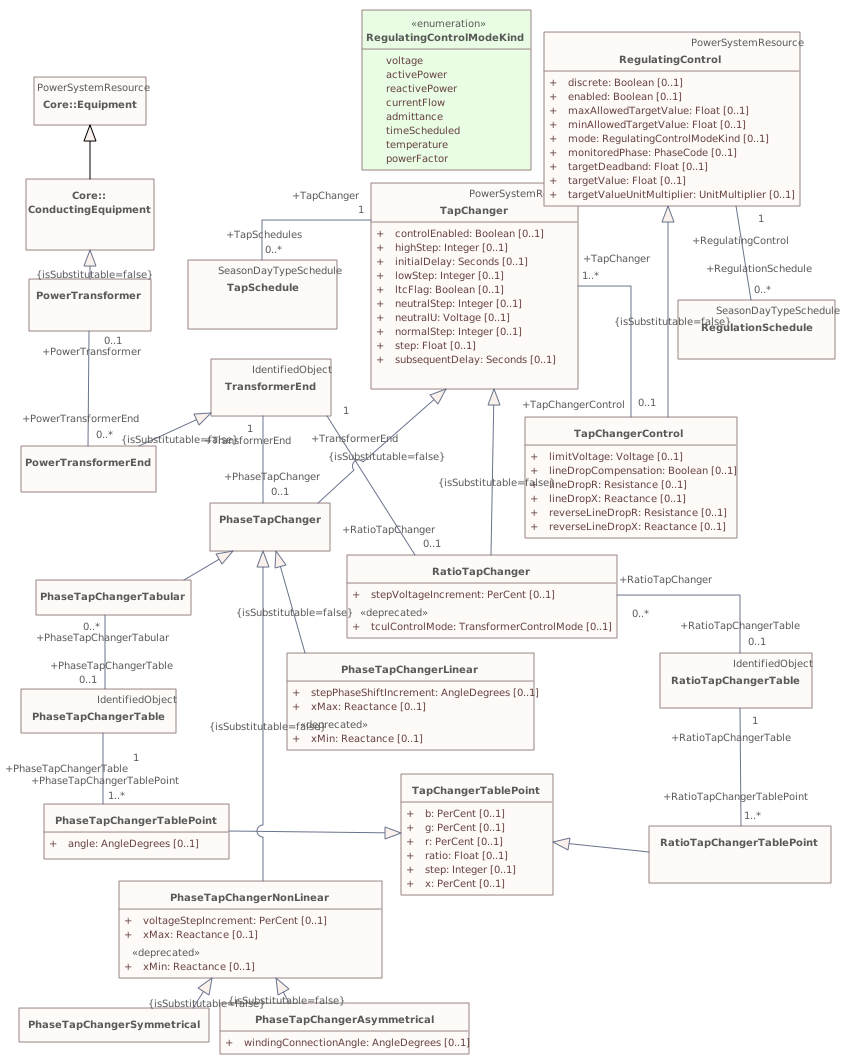
Destination
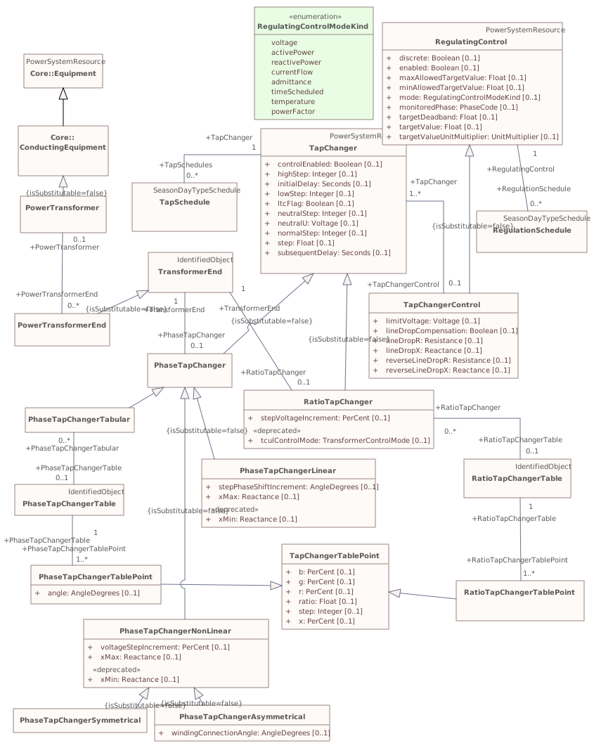
▶LoadModeli
{427D9D64-CDA2-4070-AAC6-04A32F290872}
Package notes
This package is responsible for modelling the energy consumers and the system load as curves and associated curve data. Special circumstances that may affect the load, such as seasons and day types, are also included here.
This information is used by Load Forecasting and Load Management.Package metadata — changes
| Baseline | Destination | |
|---|---|---|
| no changes | ||
Tagged values — changes
| Baseline | Destination | |
|---|---|---|
| no changes | ||
Package notes
This package is responsible for modelling the energy consumers and the system load as curves and associated curve data. Special circumstances that may affect the load, such as seasons and day types, are also included here.
This information is used by Load Forecasting and Load Management.Changed classes (3)
▶⚙ConformLoadirepresentrepresents loads that follow a daily load change pattern where the pattern can be used to scale the load with a system load.
CHANGED{B47EB000-9FCB-4543-B706-90486C3CBDD9}
Class notes (destination, redlined)
ConformLoad Class metadata — changes
| Baseline | Destination | |
|---|---|---|
| no changes | ||
Tagged values — changes
| Baseline | Destination | |
|---|---|---|
| no changes | ||
Class notes (destination, redlined)
ConformLoad Class 'ConformLoad' has no other changes. The shows its notes and every changed property.
▶⚙EnergyAreai Specializations are intended to support the load allocation function as typically required in energy management systems or planning studies to allocate hypothesized load levels to individual load points for power flow analysis. Often the energy area can be linked to both measured and forecast load levels.
CHANGED{EBAF7081-971E-4960-A0AB-B38C20682FE7}
Class notes (destination, redlined)
Describes an area having energy production or consumption.Class metadata — changes
| Baseline | Destination | |
|---|---|---|
| no changes | ||
Tagged values — changes
| Baseline | Destination | |
|---|---|---|
| no changes | ||
Class notes (destination, redlined)
Describes an area having energy production or consumption.Class 'EnergyArea' has no other changes. The shows its notes and every changed property.
▶⚙LoadResponseCharacteristici
CHANGED{F80EE4DD-B985-47e3-9832-B5005C24C87E}
Class notes (destination, redlined)
Models the characteristic response of the load demand due to changes in system conditions such as voltage and frequency. It is not related to demand response.
If LoadResponseCharacteristic.exponentModel is True, the exponential voltage or frequency dependent models are specified and used as to calculate active and reactive power components of the load model.
The equations to calculate active and reactive power components of the load model are internal to the power flow calculation, hence they use different quantities depending on the use case of the data exchange.
The equations for exponential voltage dependent load model injected power are:
pInjection= Pnominal* (Voltage/cim:BaseVoltage.nominalVoltage) ** cim:LoadResponseCharacteristic.pVoltageExponent
qInjection= Qnominal* (Voltage/cim:BaseVoltage.nominalVoltage) ** cim:LoadResponseCharacteristic.qVoltageExponent
Where:
1) * means "multiply" and ** is "raised to the power of";
2) Pnominal and Qnominal represent the active power and reactive power at nominal voltage as any load described by the voltage exponential model shall be given at nominal voltage. This means that EnergyConsumer.p and EnergyConsumer.q are at nominal voltage.
3) After power flow is solved:
-pInjection and qInjection correspond to SvPowerflow.p and SvPowerflow.q respectively.
- Voltage corresponds to SvVoltage.v at the TopologicalNode where the load is connected.Class metadata — changes
| Baseline | Destination | |
|---|---|---|
| no changes | ||
Tagged values — changes
| Baseline | Destination | |
|---|---|---|
| no changes | ||
Class notes (destination, redlined)
Models the characteristic response of the load demand due to changes in system conditions such as voltage and frequency. It is not related to demand response.
If LoadResponseCharacteristic.exponentModel is True, the exponential voltage or frequency dependent models are specified and used as to calculate active and reactive power components of the load model.
The equations to calculate active and reactive power components of the load model are internal to the power flow calculation, hence they use different quantities depending on the use case of the data exchange.
The equations for exponential voltage dependent load model injected power are:
pInjection= Pnominal* (Voltage/cim:BaseVoltage.nominalVoltage) ** cim:LoadResponseCharacteristic.pVoltageExponent
qInjection= Qnominal* (Voltage/cim:BaseVoltage.nominalVoltage) ** cim:LoadResponseCharacteristic.qVoltageExponent
Where:
1) * means "multiply" and ** is "raised to the power of";
2) Pnominal and Qnominal represent the active power and reactive power at nominal voltage as any load described by the voltage exponential model shall be given at nominal voltage. This means that EnergyConsumer.p and EnergyConsumer.q are at nominal voltage.
3) After power flow is solved:
-pInjection and qInjection correspond to SvPowerflow.p and SvPowerflow.q respectively.
- Voltage corresponds to SvVoltage.v at the TopologicalNode where the load is connected.Class 'LoadResponseCharacteristic' has no other changes. The shows its notes and every changed property.
Package 'LoadModel' has no changes to the 1 diagrams it contains.
▶Generationi
{6B50A1FD-22E9-4abc-B0B7-F46BBD8B33AE}
Package notes
This package contains packages that have information for Unit Commitment and Economic Dispatch of hydro and thermal generating units, Load Forecasting, Automatic Generation Control, and unit modeling for Training Simulation.Package metadata — changes
| Baseline | Destination | |
|---|---|---|
| no changes | ||
Tagged values — changes
| Baseline | Destination | |
|---|---|---|
| no changes | ||
Package notes
This package contains packages that have information for Unit Commitment and Economic Dispatch of hydro and thermal generating units, Load Forecasting, Automatic Generation Control, and unit modeling for Training Simulation.▶Productioni
{39719C4D-64F6-4704-8202-8CAEF5179709}
Package notes
The production package is responsible for classes which describe various kinds of generators. These classes also provide production costing information which is used to economically allocate demand among committed units and calculate reserve quantities.Package metadata — changes
| Baseline | Destination | |
|---|---|---|
| no changes | ||
Tagged values — changes
| Baseline | Destination | |
|---|---|---|
| no changes | ||
Package notes
The production package is responsible for classes which describe various kinds of generators. These classes also provide production costing information which is used to economically allocate demand among committed units and calculate reserve quantities.Changed classes (5)
▶⚙FossilFueli For example, coal, oil, gas, etc. These are the specific fuels that the generating unit can consume.
CHANGED{CEB38297-AEE1-4b55-8ECC-272DE5EDA874}
Class notes (destination, redlined)
The fossil fuel consumed by the non-nuclear thermal generating unit.Class metadata — changes
| Baseline | Destination | |
|---|---|---|
| no changes | ||
Tagged values — changes
| Baseline | Destination | |
|---|---|---|
| no changes | ||
Class notes (destination, redlined)
The fossil fuel consumed by the non-nuclear thermal generating unit.Class 'FossilFuel' has no other changes. The shows its notes and every changed property.
▶⚙FuelType«enumeration»i
CHANGED{AE75B683-1EF9-4536-B566-3EED1DAA67D6}
Class notes
Type of fuel.Class metadata — changes
| Baseline | Destination | |
|---|---|---|
| no changes | ||
Tagged values — changes
| Baseline | Destination | |
|---|---|---|
| no changes | ||
Class notes
Type of fuel.≡Attributes
| Attribute | Baseline | Destination | Notes (destination, redlined) | ||||||||||||
|---|---|---|---|---|---|---|---|---|---|---|---|---|---|---|---|
| lignitei{740E6D2B-C458-4553-B915-458358AE74A8}show details | [1..1] | [1..1] | The fuel is lignite coal. | ||||||||||||
Attribute notes (destination, redlined) The fuel is lignite coal.Attribute metadata — changes
Tagged values — changes
| |||||||||||||||
▶⚙GeneratingUniti
CHANGED{A4C4D1F8-0359-44b1-8F2A-521D3F9F3C28}
Class notes
A single or set of synchronous machines for converting mechanical power into alternating-current power. For example, individual machines within a set may be defined for scheduling purposes while a single control signal is derived for the set. In this case there would be a GeneratingUnit for each member of the set and an additional GeneratingUnit corresponding to the set.Class metadata — changes
| Baseline | Destination | |
|---|---|---|
| no changes | ||
Tagged values — changes
| Baseline | Destination | |
|---|---|---|
| no changes | ||
Class notes
A single or set of synchronous machines for converting mechanical power into alternating-current power. For example, individual machines within a set may be defined for scheduling purposes while a single control signal is derived for the set. In this case there would be a GeneratingUnit for each member of the set and an additional GeneratingUnit corresponding to the set.≡Attributes
| Attribute | Baseline | Destination | Notes (destination, redlined) | ||||||||||||
|---|---|---|---|---|---|---|---|---|---|---|---|---|---|---|---|
| governorSCDi{96994FFA-E19B-4945-A813-0EFF4E608B65}show details | PerCent [0..1] | PerCent [0..1] | Governor Speed Changer Droop. | ||||||||||||
Attribute notes (destination, redlined) Governor Speed Changer Droop.Attribute metadata — changes
Tagged values — changes
| |||||||||||||||
| nominalPi{B11EF073-DEE6-49eb-BFCB-F354BD7764CA}show details | ActivePower [0..1] | ActivePower [0..1] | The nominal power of the generating unit. | ||||||||||||
Attribute notes (destination, redlined) The nominal power of the generating unit.Attribute metadata — changes
Tagged values — changes
| |||||||||||||||
⇄Links
CHANGEDAssociation{682C859C-B9CD-4dde-A959-EB89678BBBD6}
BaselineControlAreaGeneratingUnit role ControlAreaGeneratingUnit [0..*] → GeneratingUnit role GeneratingUnit [1]
→
DestinationControlAreaGeneratingUnit role ControlAreaGeneratingUnit [0..*] → GeneratingUnit role GeneratingUnit [1]
Source end
no changes
Target end — GeneratingUnit
| Baseline | Destination | |
|---|---|---|
| RoleNote | The generating unit specified for this control area. Note that a control area should include a Generating | The generating unit specified for this control area. |
▶⚙HydroGeneratingUniti, Francis, Pelton, Kaplan).
CHANGED{2B8CC296-5CEF-4662-9FB2-48F968B7C3D9}
Class notes (destination, redlined)
A generating unit whose prime mover is a hydraulic turbine (e.g.Class metadata — changes
| Baseline | Destination | |
|---|---|---|
| no changes | ||
Tagged values — changes
| Baseline | Destination | |
|---|---|---|
| no changes | ||
Class notes (destination, redlined)
A generating unit whose prime mover is a hydraulic turbine (e.g.Class 'HydroGeneratingUnit' has no other changes. The shows its notes and every changed property.
▶⚙SolarGeneratingUniti This class does not represent photovoltaic (PV) generation.
CHANGED{C5A085AB-DDD3-41b0-91DE-9071B466AE9A}
Class notes (destination, redlined)
A solar thermal generating unit, connected to the grid by means of a rotating machine.Class metadata — changes
| Baseline | Destination | |
|---|---|---|
| no changes | ||
Tagged values — changes
| Baseline | Destination | |
|---|---|---|
| no changes | ||
Class notes (destination, redlined)
A solar thermal generating unit, connected to the grid by means of a rotating machine.Class 'SolarGeneratingUnit' has no other changes. The shows its notes and every changed property.
Package 'Production' has no changes to the 6 diagrams it contains.
Package 'Generation' has no changes to the 1 diagrams it contains.
▶DCi
{6CA575E7-020B-40d8-B841-027BF8B51BE9}
Package notes
This package contains model for direct current equipment and controls.Package metadata — changes
| Baseline | Destination | |
|---|---|---|
| no changes | ||
Tagged values — changes
| Baseline | Destination | |
|---|---|---|
| no changes | ||
Package notes
This package contains model for direct current equipment and controls.Changed classes (3)
▶⚙ACDCConverteri
CHANGED{7BAF3CFD-55A3-4945-B51F-D3117CCB7F89}
Class notes
A unit with valves for three phases, together with unit control equipment, essential protective and switching devices, DC storage capacitors, phase reactors and auxiliaries, if any, used for conversion.Class metadata — changes
| Baseline | Destination | |
|---|---|---|
| no changes | ||
Tagged values — changes
| Baseline | Destination | |
|---|---|---|
| no changes | ||
Class notes
A unit with valves for three phases, together with unit control equipment, essential protective and switching devices, DC storage capacitors, phase reactors and auxiliaries, if any, used for conversion.≡Attributes
| Attribute | Baseline | Destination | Notes (destination, redlined) | ||||||||||||
|---|---|---|---|---|---|---|---|---|---|---|---|---|---|---|---|
| idleLossi{E9ED1BC9-CA40-4d1f-91E4-5425A18765DD}show details | ActivePower [0..1] | ActivePower [0..1] | Active power loss in pole at no power transfer. It is the converter’s configuration data used in power flow. The attribute shall be a positive value. | ||||||||||||
Attribute notes (destination, redlined) Active power loss in pole at no power transfer. It is the converter’s configuration data used in power flow. The attribute shall be a positive value.Attribute metadata — changes
Tagged values — changes
| |||||||||||||||
| maxUdci{75897B30-EAA3-486e-AA11-DA02461454EE}show details | Voltage [0..1] | Voltage [0..1] | The maximum voltage on the DC side at which the converter should operate. It is the converter’s configuration data used in power flow. The attribute shall be a positive value. | ||||||||||||
Attribute notes (destination, redlined) The maximum voltage on the DC side at which the converter should operate. It is the converter’s configuration data used in power flow. The attribute shall be a positive value.Attribute metadata — changes
Tagged values — changes
| |||||||||||||||
| minUdci{C442EC69-4FD8-4b00-A7A5-9356A9E1C4BF}show details | Voltage [0..1] | Voltage [0..1] | The minimum voltage on the DC side at which the converter should operate. It is the converter’s configuration data used in power flow. The attribute shall be a positive value. | ||||||||||||
Attribute notes (destination, redlined) The minimum voltage on the DC side at which the converter should operate. It is the converter’s configuration data used in power flow. The attribute shall be a positive value.Attribute metadata — changes
Tagged values — changes
| |||||||||||||||
| ratedUdci{85D36F1D-363A-42a6-ACDB-87AE5511D72F}show details | Voltage [0..1] | Voltage [0..1] | Rated converter DC voltage, also called UdN. The attribute shall be a positive value. It is the converter’s configuration data used in power flow. For instance a bipolar HVDC link with value 200 kV has a 400kV difference between the dc lines. | ||||||||||||
Attribute notes (destination, redlined) Rated converter DC voltage, also called UdN. The attribute shall be a positive value. It is the converter’s configuration data used in power flow. For instance a bipolar HVDC link with value 200 kV has a 400kV difference between the dc lines.Attribute metadata — changes
Tagged values — changes
| |||||||||||||||
| resistiveLossi{170A8A5E-A487-4e0a-A458-C5CEA87D3624}show details | Resistance [0..1] | Resistance [0..1] | It is the converter’s configuration data used in power flow. Refer to poleLossP. The attribute shall be a positive value. | ||||||||||||
Attribute notes (destination, redlined) It is the converter’s configuration data used in power flow. Refer to poleLossP. The attribute shall be a positive value.Attribute metadata — changes
Tagged values — changes
| |||||||||||||||
▶⚙CsConverteridcDC voltage, dc current and active power. From a steady state perspective it is sufficient to specify the wanteddesired active power transfer (ACDCConverter.targetPpcc) and the control functions will set the dc voltage, dc current, firing angle, transformer tap position and number of connected filters to meet this. Therefore attributes targetAlpha and targetGamma are not applicable in this case.
The reactive power consumed by the converter is a function of the firing angle, transformer tap position and number of connected filter, which can be approximated with half of the active power. The losses isare a function of the dc voltage and dc current.
The attributes minAlpha and maxAlpha define the range of firing angles for rectifier operation between which no discrete tap changer action takes place. The range is typically 10- to 18 degrees.
The attributes minGamma and maxGamma define the range of extinction angles for inverter operation between which no discrete tap changer action takes place. The range is typically 17- to 20 degrees.
CHANGED{A4B7CE00-5051-45cf-B107-CD62C2FF3B81}
Class notes (destination, redlined)
DC side of the current source converter (CSC).
The firing angle controls the dc voltage at the converter, both for rectifier and inverter. The difference between the dc voltages of the rectifier and inverter determines the dc current. The extinction angle is used to limit the dc voltage at the inverter, if needed, and is not used in active power control. The firing angle, transformer tap position and number of connected filters are the primary means to control a current source dc line. Higher level controls are built on top, e.g. Class metadata — changes
| Baseline | Destination | |
|---|---|---|
| no changes | ||
Tagged values — changes
| Baseline | Destination | |
|---|---|---|
| no changes | ||
Class notes (destination, redlined)
DC side of the current source converter (CSC).
The firing angle controls the dc voltage at the converter, both for rectifier and inverter. The difference between the dc voltages of the rectifier and inverter determines the dc current. The extinction angle is used to limit the dc voltage at the inverter, if needed, and is not used in active power control. The firing angle, transformer tap position and number of connected filters are the primary means to control a current source dc line. Higher level controls are built on top, e.g. ≡Attributes
| Attribute | Baseline | Destination | Notes (destination, redlined) | ||||||||||||
|---|---|---|---|---|---|---|---|---|---|---|---|---|---|---|---|
| alphai{9D272F46-EABD-436f-9B05-3AB954FEB505}show details | AngleDegrees [0..1] | AngleDegrees [0..1] | Firing angle that determines the | ||||||||||||
Attribute notes (destination, redlined) Firing angle that determines the Attribute metadata — changes
Tagged values — changes
| |||||||||||||||
| gammai{B9AD7780-6511-4795-8FF2-0797C537AF64}show details | AngleDegrees [0..1] | AngleDegrees [0..1] | Extinction angle. It is used to limit the | ||||||||||||
Attribute notes (destination, redlined) Extinction angle. It is used to limit the Attribute metadata — changes
Tagged values — changes
| |||||||||||||||
| maxAlphai{35DA4A07-8966-4207-B9EA-CFA2F8C5556C}show details | AngleDegrees [0..1] | AngleDegrees [0..1] | Maximum firing angle. It is the converter’s configuration data used in power flow. The attribute shall be a positive value. | ||||||||||||
Attribute notes (destination, redlined) Maximum firing angle. It is the converter’s configuration data used in power flow. The attribute shall be a positive value.Attribute metadata — changes
Tagged values — changes
| |||||||||||||||
| maxGammai{CAAD51DE-696B-4678-8DEA-868AFA1529B4}show details | AngleDegrees [0..1] | AngleDegrees [0..1] | Maximum extinction angle. It is the converter’s configuration data used in power flow. The attribute shall be a positive value. | ||||||||||||
Attribute notes (destination, redlined) Maximum extinction angle. It is the converter’s configuration data used in power flow. The attribute shall be a positive value.Attribute metadata — changes
Tagged values — changes
| |||||||||||||||
| maxIdci{6C080741-A57E-4534-A156-2380B3E712ED}show details | CurrentFlow [0..1] | CurrentFlow [0..1] | The maximum direct current (Id) on the DC side at which the converter should operate. It is the converter’s configuration data use in power flow. The attribute shall be a positive value. | ||||||||||||
Attribute notes (destination, redlined) The maximum direct current (Id) on the DC side at which the converter should operate. It is the converter’s configuration data use in power flow. The attribute shall be a positive value.Attribute metadata — changes
Tagged values — changes
| |||||||||||||||
| minAlphai{ADAF6A15-8626-4955-BD2A-A3EE3D700C84}show details | AngleDegrees [0..1] | AngleDegrees [0..1] | Minimum firing angle. It is the converter’s configuration data used in power flow. The attribute shall be a positive value. | ||||||||||||
Attribute notes (destination, redlined) Minimum firing angle. It is the converter’s configuration data used in power flow. The attribute shall be a positive value.Attribute metadata — changes
Tagged values — changes
| |||||||||||||||
| minGammai{601E21E7-7AFC-4631-9752-EE3F81D1BEF5}show details | AngleDegrees [0..1] | AngleDegrees [0..1] | Minimum extinction angle. It is the converter’s configuration data used in power flow. The attribute shall be a positive value. | ||||||||||||
Attribute notes (destination, redlined) Minimum extinction angle. It is the converter’s configuration data used in power flow. The attribute shall be a positive value.Attribute metadata — changes
Tagged values — changes
| |||||||||||||||
| minIdci{27F20192-3FDA-4372-8F7C-B0D934DD9B2C}show details | CurrentFlow [0..1] | CurrentFlow [0..1] | The minimum direct current (Id) on the DC side at which the converter should operate. It is the converter’s configuration data used in power flow. The attribute shall be a positive value. | ||||||||||||
Attribute notes (destination, redlined) The minimum direct current (Id) on the DC side at which the converter should operate. It is the converter’s configuration data used in power flow. The attribute shall be a positive value.Attribute metadata — changes
Tagged values — changes
| |||||||||||||||
| ratedIdci{F988CC98-3A7A-401b-B41F-1A8A47BFFE99}show details | CurrentFlow [0..1] | CurrentFlow [0..1] | Rated converter DC current, also called IdN. The attribute shall be a positive value. It is the converter’s configuration data used in power flow. | ||||||||||||
Attribute notes (destination, redlined) Rated converter DC current, also called IdN. The attribute shall be a positive value. It is the converter’s configuration data used in power flow.Attribute metadata — changes
Tagged values — changes
| |||||||||||||||
▶⚙DCEquipmentContaineriEquipmentContanerEquipmentContainer for AC in that it may also contain DCNode(-s). Hence it can contain both AC and DC equipment.
CHANGED{B7EB57A9-3AD6-40e2-9D5D-F391283E63B3}
Class notes (destination, redlined)
A modelling construct to provide a root class for containment of DC as well as AC equipment. The class differ from the Class metadata — changes
| Baseline | Destination | |
|---|---|---|
| no changes | ||
Tagged values — changes
| Baseline | Destination | |
|---|---|---|
| no changes | ||
Class notes (destination, redlined)
A modelling construct to provide a root class for containment of DC as well as AC equipment. The class differ from the Class 'DCEquipmentContainer' has no other changes. The shows its notes and every changed property.
Changed diagrams (2)
▶▦ACDCConnectivityModeli
CHANGED{43531300-1039-4de2-880E-A73AFC65A581}
Diagram notes
This diagram shows connectivity and topology model for both AC and DC networks.Diagram metadata — changes
| Baseline | Destination | |
|---|---|---|
| ModifiedDate | 2019-03-05 13:20:31 | 2020-06-16 14:29:42 |
Diagram notes
This diagram shows connectivity and topology model for both AC and DC networks.▤Metadata
| Baseline | Destination | |
|---|---|---|
| ModifiedDate | 2019-03-05 13:20:31 | 2020-06-16 14:29:42 |
▦Diagram
moved or resized
Baseline
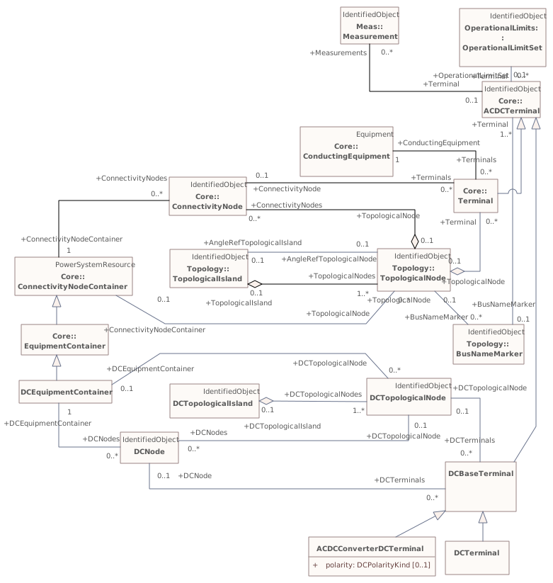
Destination
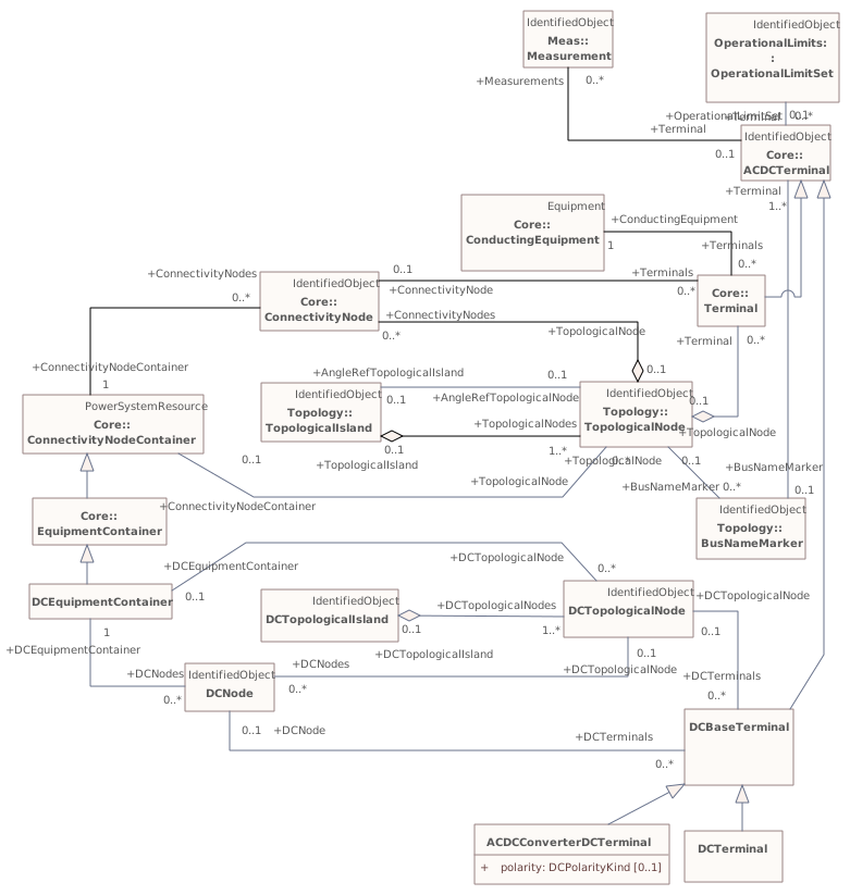
▶▦ACDCConverteri
CHANGED{D8B07844-D3DD-4829-B42B-24F6109C6F13}
Diagram notes
This diagram shows classes used to model DC converters.Diagram metadata — changes
| Baseline | Destination | |
|---|---|---|
| ModifiedDate | 2019-10-24 10:00:07 | 2020-06-30 13:55:52 |
Diagram notes
This diagram shows classes used to model DC converters.▤Metadata
| Baseline | Destination | |
|---|---|---|
| ModifiedDate | 2019-10-24 10:00:07 | 2020-06-30 13:55:52 |
Diagram 'ACDCConverter' has no other changes. The shows its notes and every changed property.
▶Equivalentsi
{32F75AB7-7839-4933-BE8C-F162A464FE41}
Package notes
The equivalents package models equivalent networks.Package metadata — changes
| Baseline | Destination | |
|---|---|---|
| no changes | ||
Tagged values — changes
| Baseline | Destination | |
|---|---|---|
| no changes | ||
Package notes
The equivalents package models equivalent networks.Changed classes (1)
▶⚙EquivalentInjectioni
CHANGED{9749AD93-8F33-48c8-9291-02B9D671C172}
Class notes
This class represents equivalent injections (generation or load). Voltage regulation is allowed only at the point of connection.Class metadata — changes
| Baseline | Destination | |
|---|---|---|
| no changes | ||
Tagged values — changes
| Baseline | Destination | |
|---|---|---|
| no changes | ||
Class notes
This class represents equivalent injections (generation or load). Voltage regulation is allowed only at the point of connection.≡Attributes
| Attribute | Baseline | Destination | Notes (destination, redlined) | ||||||||||||
|---|---|---|---|---|---|---|---|---|---|---|---|---|---|---|---|
| maxQi{D033683B-6C04-4090-94B3-212F9C58C3A6}show details | ReactivePower [0..1] | ReactivePower [0..1] | Maximum reactive power of the injection. Used for modelling of infeed for load flow exchange. Not used for short circuit modelling. | ||||||||||||
Attribute notes (destination, redlined) Maximum reactive power of the injection. Used for modelling of infeed for load flow exchange. Not used for short circuit modelling.Attribute metadata — changes
Tagged values — changes
| |||||||||||||||
| minQi{D4D5B759-8DC7-41ec-BFEE-EF85D3E20724}show details | ReactivePower [0..1] | ReactivePower [0..1] | Minimum reactive power of the injection. Used for modelling of infeed for load flow exchange. Not used for short circuit modelling. | ||||||||||||
Attribute notes (destination, redlined) Minimum reactive power of the injection. Used for modelling of infeed for load flow exchange. Not used for short circuit modelling.Attribute metadata — changes
Tagged values — changes
| |||||||||||||||
Package 'Equivalents' has no changes to the 1 diagrams it contains.
▶AuxiliaryEquipmenti
{FF7DBBED-8801-4db6-A94B-3AE5E6FFFE95}
Package notes
Contains equipment which is not normal conducting equipment such as sensors, fault locators, and surge protectors. These devices do not define power carrying topological connections as conducting equipment, but are associated to terminals of other conducting equipment.Package metadata — changes
| Baseline | Destination | |
|---|---|---|
| no changes | ||
Tagged values — changes
| Baseline | Destination | |
|---|---|---|
| no changes | ||
Package notes
Contains equipment which is not normal conducting equipment such as sensors, fault locators, and surge protectors. These devices do not define power carrying topological connections as conducting equipment, but are associated to terminals of other conducting equipment.Changed classes (2)
▶⚙AuxiliaryEquipmenti
CHANGED{CB6ECCEF-5854-40ec-A5DD-6A4E884E859C}
Class notes (destination, redlined)
AuxiliaryEquipment describe equipment that is not performing any primary functions but support for the equipment performing the primary function.
AuxiliaryEquipment is attached to primary equipment via an association with Terminal.
This class is for AC equipment only.Class metadata — changes
| Baseline | Destination | |
|---|---|---|
| no changes | ||
Tagged values — changes
| Baseline | Destination | |
|---|---|---|
| no changes | ||
Class notes (destination, redlined)
AuxiliaryEquipment describe equipment that is not performing any primary functions but support for the equipment performing the primary function.
AuxiliaryEquipment is attached to primary equipment via an association with Terminal.
This class is for AC equipment only.Class 'AuxiliaryEquipment' has no other changes. The shows its notes and every changed property.
▶⚙WaveTrapiLineWave traps are devices that impede high frequency power line carrier signals yet present a negligible impedance at the main power frequency.
CHANGED{3519E53B-C18B-48f6-9E29-18D73223B91B}
Class notes (destination, redlined)
Class metadata — changes
| Baseline | Destination | |
|---|---|---|
| no changes | ||
Tagged values — changes
| Baseline | Destination | |
|---|---|---|
| no changes | ||
Class notes (destination, redlined)
Class 'WaveTrap' has no other changes. The shows its notes and every changed property.
Changed diagrams (1)
▶▦AuxiliaryEquipmenti
CHANGED{8B0885F9-C9C1-47ba-B331-E122DA4B4763}
Diagram notes
Inheritance and associations for auxiliary equipment.Diagram metadata — changes
| Baseline | Destination | |
|---|---|---|
| ModifiedDate | 2019-09-20 08:50:55 | 2020-09-02 12:57:48 |
Diagram notes
Inheritance and associations for auxiliary equipment.▤Metadata
| Baseline | Destination | |
|---|---|---|
| ModifiedDate | 2019-09-20 08:50:55 | 2020-09-02 12:57:48 |
Diagram 'AuxiliaryEquipment' has no other changes. The shows its notes and every changed property.
▶Measi
{6B58A5C3-5CC1-4320-A9D3-2CABB8F9399E}
Package notes
Contains entities that describe dynamic measurement data exchanged between applications.Package metadata — changes
| Baseline | Destination | |
|---|---|---|
| no changes | ||
Tagged values — changes
| Baseline | Destination | |
|---|---|---|
| no changes | ||
Package notes
Contains entities that describe dynamic measurement data exchanged between applications.Changed classes (5)
▶⚙Analogi
CHANGED{BBCB109C-256C-42ee-9B78-8B17B54C9668}
Class notes
Analog represents an analog Measurement.Class metadata — changes
| Baseline | Destination | |
|---|---|---|
| no changes | ||
Tagged values — changes
| Baseline | Destination | |
|---|---|---|
| no changes | ||
Class notes
Analog represents an analog Measurement.≡Attributes
| Attribute | Baseline | Destination | Notes (destination, redlined) | ||||||||||||
|---|---|---|---|---|---|---|---|---|---|---|---|---|---|---|---|
| positiveFlowIni{25855E61-5D6B-4b06-A221-C580AF35A5D5}show details | Boolean [0..1] | Boolean [0..1] | |||||||||||||
Attribute notes (destination, redlined) Attribute metadata — changes
Tagged values — changes
| |||||||||||||||
▶⚙Controli
CHANGED{4EEEE27D-42CD-4efc-8F74-3655BF703F4E}
Class notes
Control is used for supervisory/device control. It represents control outputs that are used to change the state in a process, e.g. close or open breaker, a set point value or a raise lower command.Class metadata — changes
| Baseline | Destination | |
|---|---|---|
| no changes | ||
Tagged values — changes
| Baseline | Destination | |
|---|---|---|
| no changes | ||
Class notes
Control is used for supervisory/device control. It represents control outputs that are used to change the state in a process, e.g. close or open breaker, a set point value or a raise lower command.⇄Links
CHANGEDAssociation{55F3693A-6960-486a-AEB0-EEBB67B10D9A}
→
Source end — ControlAction
| Baseline | Destination | |
|---|---|---|
| RoleNote | The control action that is performed on the control | (empty) |
Target end — Control
| Baseline | Destination | |
|---|---|---|
| RoleNote | The control that the control action is performed on. | (empty) |
▶⚙Measurementi
CHANGED{AB1758FA-3A4D-478f-BE4F-ADC8E2F886CC}
Class notes
A Measurement represents any measured, calculated or non-measured non-calculated quantity. Any piece of equipment may contain Measurements, e.g. a substation may have temperature measurements and door open indications, a transformer may have oil temperature and tank pressure measurements, a bay may contain a number of power flow measurements and a Breaker may contain a switch status measurement.
The PSR - Measurement association is intended to capture this use of Measurement and is included in the naming hierarchy based on EquipmentContainer. The naming hierarchy typically has Measurements as leaves, e.g. Substation-VoltageLevel-Bay-Switch-Measurement.
Some Measurements represent quantities related to a particular sensor location in the network, e.g. a voltage transformer (VT) or potential transformer (PT) at a busbar or a current transformer (CT) at the bar between a breaker and an isolator. The sensing position is not captured in the PSR - Measurement association. Instead it is captured by the Measurement - Terminal association that is used to define the sensing location in the network topology. The location is defined by the connection of the Terminal to ConductingEquipment.
If both a Terminal and PSR are associated, and the PSR is of type ConductingEquipment, the associated Terminal should belong to that ConductingEquipment instance.
When the sensor location is needed both Measurement-PSR and Measurement-Terminal are used. The Measurement-Terminal association is never used alone.Class metadata — changes
| Baseline | Destination | |
|---|---|---|
| no changes | ||
Tagged values — changes
| Baseline | Destination | |
|---|---|---|
| no changes | ||
Class notes
A Measurement represents any measured, calculated or non-measured non-calculated quantity. Any piece of equipment may contain Measurements, e.g. a substation may have temperature measurements and door open indications, a transformer may have oil temperature and tank pressure measurements, a bay may contain a number of power flow measurements and a Breaker may contain a switch status measurement.
The PSR - Measurement association is intended to capture this use of Measurement and is included in the naming hierarchy based on EquipmentContainer. The naming hierarchy typically has Measurements as leaves, e.g. Substation-VoltageLevel-Bay-Switch-Measurement.
Some Measurements represent quantities related to a particular sensor location in the network, e.g. a voltage transformer (VT) or potential transformer (PT) at a busbar or a current transformer (CT) at the bar between a breaker and an isolator. The sensing position is not captured in the PSR - Measurement association. Instead it is captured by the Measurement - Terminal association that is used to define the sensing location in the network topology. The location is defined by the connection of the Terminal to ConductingEquipment.
If both a Terminal and PSR are associated, and the PSR is of type ConductingEquipment, the associated Terminal should belong to that ConductingEquipment instance.
When the sensor location is needed both Measurement-PSR and Measurement-Terminal are used. The Measurement-Terminal association is never used alone.⇄Links
CHANGEDAssociation{016DD996-A1EA-4bb6-8349-AF38EEDFF7AD}
→
Source end — Asset
| Baseline | Destination | |
|---|---|---|
| RoleNote | Asset that has a measurement | (empty) |
Target end
no changes
CHANGEDAssociation{0566ECD1-879E-43fc-AFB0-A8B79BFC4DEE}
→
Source end — MeasurementAction
| Baseline | Destination | |
|---|---|---|
| RoleNote | The measurement action that is performed on the measurement | (empty) |
Target end — Measurement
| Baseline | Destination | |
|---|---|---|
| RoleNote | The measurement that the measurement action is performed on | (empty) |
CHANGEDAssociation{F582AAC6-446D-49be-9380-09E21CAA0CCF}
→
Source end — Locations
| Baseline | Destination | |
|---|---|---|
| RoleNote | Location of this measurement. | (empty) |
Target end — Measurements
| Baseline | Destination | |
|---|---|---|
| RoleNote | All measurements at this location. | (empty) |
▶⚙MeasurementValuei
CHANGED{E6D7B57A-456A-43b5-838B-3CFB466EE4C4}
Class notes
The current state for a measurement. A state value is an instance of a measurement from a specific source. Measurements can be associated with many state values, each representing a different source for the measurement.Class metadata — changes
| Baseline | Destination | |
|---|---|---|
| no changes | ||
Tagged values — changes
| Baseline | Destination | |
|---|---|---|
| no changes | ||
Class notes
The current state for a measurement. A state value is an instance of a measurement from a specific source. Measurements can be associated with many state values, each representing a different source for the measurement.⇄Links
CHANGEDAssociation{A0C93754-F2B4-4597-96C0-BDCA60E5BC09}
BaselineProcedureDataSet role ProcedureDataSet [0..*] → MeasurementValue role MeasurementValue [0..*]
→
DestinationProcedureDataSet role ProcedureDataSet [0..*] → MeasurementValue role MeasurementValue [0..*]
Source end — ProcedureDataSet
| Baseline | Destination | |
|---|---|---|
| RoleNote | Procedure data set that applies to this mesurement value. | (empty) |
Target end — MeasurementValue
| Baseline | Destination | |
|---|---|---|
| RoleNote | Measurement value related to this procedure data set. | (empty) |
▶⚙Quality61850i
CHANGED{3561961B-F3BD-41f7-B693-9D9F77C613A0}
Class notes
Quality flags in this class are as defined in IEC 61850, except for estimatorReplaced, which has been included in this class for convenience.Class metadata — changes
| Baseline | Destination | |
|---|---|---|
| no changes | ||
Tagged values — changes
| Baseline | Destination | |
|---|---|---|
| no changes | ||
Class notes
Quality flags in this class are as defined in IEC 61850, except for estimatorReplaced, which has been included in this class for convenience.≡Attributes
| Attribute | Baseline | Destination | Notes (destination, redlined) | ||||||||||||
|---|---|---|---|---|---|---|---|---|---|---|---|---|---|---|---|
| estimatorReplacedi{11CA6A0B-FEAC-41a0-AF45-AE159D352461}show details | Boolean [0..1] | Boolean [0..1] | Value has been replaced by State Estimator. estimatorReplaced is not an | ||||||||||||
Attribute notes (destination, redlined) Value has been replaced by State Estimator. estimatorReplaced is not an Attribute metadata — changes
Tagged values — changes
| |||||||||||||||
Package 'Meas' has no changes to the 5 diagrams it contains.
▶Topologyi
{E44AA599-D1DD-4d0c-8487-AE8BE9E6FEEB}
Package notes
An extension to the Core Package that, in association with the Terminal class, models Connectivity, that is the physical definition of how equipment is connected together. In addition it models Topology, that is the logical definition of how equipment is connected via closed switches. The Topology definition is independent of the other electrical characteristics.Package metadata — changes
| Baseline | Destination | |
|---|---|---|
| no changes | ||
Tagged values — changes
| Baseline | Destination | |
|---|---|---|
| no changes | ||
Package notes
An extension to the Core Package that, in association with the Terminal class, models Connectivity, that is the physical definition of how equipment is connected together. In addition it models Topology, that is the logical definition of how equipment is connected via closed switches. The Topology definition is independent of the other electrical characteristics.Changed classes (2)
▶⚙BusNameMarkeri The associated terminals are normally connected by non-retained switches. For a ring bus station configuration, all BusbarSection terminals in the ring are typically associated. For a breaker and a half scheme, both BusbarSections would normally be associated. For a ring bus, all BusbarSections would normally be associated. For a "straight" busbar configuration, normally only the main terminal at the BusbarSection would be associated.
CHANGED{CC2E7414-F646-406e-BFE1-86C1E97305FA}
Class notes (destination, redlined)
Used to apply user standard names to TopologicalNodes. Associated with one or more terminals that are normally connected with the bus name.Class metadata — changes
| Baseline | Destination | |
|---|---|---|
| no changes | ||
Tagged values — changes
| Baseline | Destination | |
|---|---|---|
| no changes | ||
Class notes (destination, redlined)
Used to apply user standard names to TopologicalNodes. Associated with one or more terminals that are normally connected with the bus name.⇄Links
CHANGEDAssociation{33820695-1C8F-47c2-96B4-E770AF9728EF}
→
Source end
no changes
Target end — TopologicalNode
| Baseline | Destination | |
|---|---|---|
| RoleNote | A user defined topological node that was originally defined in a planning model not yet having topology described by Connectivity | A user defined topological node that was originally defined in a planning model not yet having topology described by ConnectivityNodes. Once ConnectivityNodes |
▶⚙TopologicalNodei
CHANGED{82489582-0ECB-4066-970D-A265B1065315}
Class notes
For a detailed substation model a topological node is a set of connectivity nodes that, in the current network state, are connected together through any type of closed switches, including jumpers. Topological nodes change as the current network state changes (i.e., switches, breakers, etc. change state).
For a planning model, switch statuses are not used to form topological nodes. Instead they are manually created or deleted in a model builder tool. Topological nodes maintained this way are also called "busses".Class metadata — changes
| Baseline | Destination | |
|---|---|---|
| no changes | ||
Tagged values — changes
| Baseline | Destination | |
|---|---|---|
| no changes | ||
Class notes
For a detailed substation model a topological node is a set of connectivity nodes that, in the current network state, are connected together through any type of closed switches, including jumpers. Topological nodes change as the current network state changes (i.e., switches, breakers, etc. change state).
For a planning model, switch statuses are not used to form topological nodes. Instead they are manually created or deleted in a model builder tool. Topological nodes maintained this way are also called "busses".⇄Links
CHANGEDAssociation{33820695-1C8F-47c2-96B4-E770AF9728EF}
→
Source end
no changes
Target end — TopologicalNode
| Baseline | Destination | |
|---|---|---|
| RoleNote | A user defined topological node that was originally defined in a planning model not yet having topology described by Connectivity | A user defined topological node that was originally defined in a planning model not yet having topology described by ConnectivityNodes. Once ConnectivityNodes |
Package 'Topology' has no changes to the 2 diagrams it contains.
▶OperationalLimitsi
{CCAAF4EA-4C50-4438-86F9-63852950B3CA}
Package notes
This package models a specification of limits associated with equipment and other operational entities.Package metadata — changes
| Baseline | Destination | |
|---|---|---|
| no changes | ||
Tagged values — changes
| Baseline | Destination | |
|---|---|---|
| no changes | ||
Package notes
This package models a specification of limits associated with equipment and other operational entities.Changed classes (1)
▶⚙OperationalLimitSeti Sets of limits might apply to a specific temperature, or season for example. A set of limits may contain different severities of limit levels that would apply to the same equipment. The set may contain limits of different types such as apparent power and current limits or high and low voltage limits that are logically applied together as a set.
CHANGED{B0D1133E-CFA4-467d-81D1-75719BF02976}
Class notes (destination, redlined)
A set of limits associated with equipment.Class metadata — changes
| Baseline | Destination | |
|---|---|---|
| no changes | ||
Tagged values — changes
| Baseline | Destination | |
|---|---|---|
| no changes | ||
Class notes (destination, redlined)
A set of limits associated with equipment.Class 'OperationalLimitSet' has no other changes. The shows its notes and every changed property.
Package 'OperationalLimits' has no changes to the 2 diagrams it contains.
▶ControlAreai
{3A4198A2-F8DC-4ff1-B669-3064688AF4DD}
Package notes
The ControlArea package models area specifications which can be used for a variety of purposes. The package as a whole models potentially overlapping control area specifications for the purpose of actual generation control, load forecast area load capture, or powerflow based analysis.Package metadata — changes
| Baseline | Destination | |
|---|---|---|
| no changes | ||
Tagged values — changes
| Baseline | Destination | |
|---|---|---|
| no changes | ||
Package notes
The ControlArea package models area specifications which can be used for a variety of purposes. The package as a whole models potentially overlapping control area specifications for the purpose of actual generation control, load forecast area load capture, or powerflow based analysis.Changed classes (2)
▶⚙ControlAreaicanmay be superimposed on the physical model. The following general principles apply to ControlArea:
1. The control area orientation for net interchange is positive for an import, negative for an export.
2. The control area net interchange is determined by summing flows in Terminals. The Terminals are identified by creating a set of TieFlow objects associated with a ControlArea object. Each TieFlow object identifies one Terminal.
3. In a single network model, a tie between two control areas must be modelled in both control area specifications, such that the two representations of the tie flow sum to zero.
4. The normal orientation of Terminal flow is positive for flow into the conducting equipment that owns the Terminal. (i.e. flow from a bus into a device is positive.) However, the orientation of each flow in the control area specification must align with the control area convention, i.e. import is positive. If the orientation of the Terminal flow referenced by a TieFlow is positive into the control area, then this is confirmed by setting TieFlow.positiveFlowIn flag TRUE. If not, the orientation must be reversed by setting the TieFlow.positiveFlowIn flag FALSE.
CHANGED{EB35F9FE-F63C-47f6-B2E8-774B9B2735C8}
Class notes (destination, redlined)
A control area is a grouping of generating units and/or loads and a cutset of tie lines (as terminals) which may be used for a variety of purposes including automatic generation control, power flow solution area interchange control specification, and input to load forecasting. All generation and load within the area defined by the terminals on the border are considered in the area interchange control. Note that any number of overlapping control area specifications Class metadata — changes
| Baseline | Destination | |
|---|---|---|
| no changes | ||
Tagged values — changes
| Baseline | Destination | |
|---|---|---|
| no changes | ||
Class notes (destination, redlined)
A control area is a grouping of generating units and/or loads and a cutset of tie lines (as terminals) which may be used for a variety of purposes including automatic generation control, power flow solution area interchange control specification, and input to load forecasting. All generation and load within the area defined by the terminals on the border are considered in the area interchange control. Note that any number of overlapping control area specifications Class 'ControlArea' has no other changes. The shows its notes and every changed property.
▶⚙ControlAreaGeneratingUniti It should be noted that only one instance within a control area should reference a specific generating unit.
CHANGED{F60BBA5C-76E4-4429-8437-2846CBBD9480}
Class notes (destination, redlined)
A control area generating unit. This class is needed so that alternate control area definitions may include the same generating unit.Class metadata — changes
| Baseline | Destination | |
|---|---|---|
| no changes | ||
Tagged values — changes
| Baseline | Destination | |
|---|---|---|
| no changes | ||
Class notes (destination, redlined)
A control area generating unit. This class is needed so that alternate control area definitions may include the same generating unit.⇄Links
CHANGEDAssociation{682C859C-B9CD-4dde-A959-EB89678BBBD6}
BaselineControlAreaGeneratingUnit role ControlAreaGeneratingUnit [0..*] → GeneratingUnit role GeneratingUnit [1]
→
DestinationControlAreaGeneratingUnit role ControlAreaGeneratingUnit [0..*] → GeneratingUnit role GeneratingUnit [1]
Source end
no changes
Target end — GeneratingUnit
| Baseline | Destination | |
|---|---|---|
| RoleNote | The generating unit specified for this control area. Note that a control area should include a Generating | The generating unit specified for this control area. |
Package 'ControlArea' has no changes to the 3 diagrams it contains.
▶Faultsi
{59BC9A2E-B8E4-4c5f-B1D8-2C6502296346}
Package notes
The package describes faults that may happen to conducting equipment, e.g. tree falling on a power line.Package metadata — changes
| Baseline | Destination | |
|---|---|---|
| no changes | ||
Tagged values — changes
| Baseline | Destination | |
|---|---|---|
| no changes | ||
Package notes
The package describes faults that may happen to conducting equipment, e.g. tree falling on a power line.Changed classes (2)
▶⚙Faulti
CHANGED{73ABECF2-4B28-4c55-8665-0882A2C8BCA4}
Class notes
Abnormal condition causing current flow through conducting equipment, such as caused by equipment failure or short circuits from objects not typically modelled (for example, a tree falling on a line).Class metadata — changes
| Baseline | Destination | |
|---|---|---|
| no changes | ||
Tagged values — changes
| Baseline | Destination | |
|---|---|---|
| no changes | ||
Class notes
Abnormal condition causing current flow through conducting equipment, such as caused by equipment failure or short circuits from objects not typically modelled (for example, a tree falling on a line).⇄Links
CHANGEDAssociation{7F84E357-68DD-4257-BD11-EE226FADA1E6}
→
Source end — Fault
| Baseline | Destination | |
|---|---|---|
| RoleNote | All faults at this location. | (empty) |
Target end — Location
| Baseline | Destination | |
|---|---|---|
| RoleNote | Location of this fault. | (empty) |
▶⚙FaultCauseTypei
CHANGED{FA0CB393-8E7C-411c-B4F1-14073D940EED}
Class notes
Type of cause of the fault.Class metadata — changes
| Baseline | Destination | |
|---|---|---|
| no changes | ||
Tagged values — changes
| Baseline | Destination | |
|---|---|---|
| no changes | ||
Class notes
Type of cause of the fault.⇄Links
CHANGEDAssociation{B79138C2-DB7B-43a8-A72B-77D615EB381B}
→
DestinationConfigurationEvent role ConfigurationEvent [0..*] → FaultCauseType role FaultCauseType [1]
Link metadata
| Baseline | Destination | |
|---|---|---|
| Stereotype | (empty) | Part 3 Ext |
Source end — ConfigurationEvent
| Baseline | Destination | |
|---|---|---|
| RoleNote | All configuration events created for this fault cause type. | (empty) |
| Stereotype | (empty) | Part 3 Ext |
Target end — FaultCauseType
| Baseline | Destination | |
|---|---|---|
| RoleNote | Fault cause type whose change resulted in this configuration event. | (empty) |
| Stereotype | (empty) | Part 3 Ext |
Package 'Faults' has no changes to the 1 diagrams it contains.
▶Dynamicsi
{A71B9185-6D48-40f4-B618-485C08C4F269}
Package notes
The CIM dynamic model definitions reflect the most common IEEE or, in the case of wind models, IEC, representations of models as well as models included in some of the transient stability software widely used by utilities.
These dynamic models are intended to ensure interoperability between different vendors’ software products currently in use by electric utility energy companies, utilities, Transmission System Operators (TSOs), Regional Transmission Organizations (RTOs), and Independent System Operators (ISOs). It is important to note that each vendor is free to select its own internal implementation of these models. Differences in vendor results, as long as they are within accepted engineering practice, caused by different internal representations, are acceptable.
Unless explicitly stated otherwise, the following modelling conventions are followed:
- limited integrators are of the non-windup type;
- it shall be possible to enter a time constant of zero (where it makes sense).Package metadata — changes
| Baseline | Destination | |
|---|---|---|
| no changes | ||
Tagged values — changes
| Baseline | Destination | |
|---|---|---|
| no changes | ||
Package notes
The CIM dynamic model definitions reflect the most common IEEE or, in the case of wind models, IEC, representations of models as well as models included in some of the transient stability software widely used by utilities.
These dynamic models are intended to ensure interoperability between different vendors’ software products currently in use by electric utility energy companies, utilities, Transmission System Operators (TSOs), Regional Transmission Organizations (RTOs), and Independent System Operators (ISOs). It is important to note that each vendor is free to select its own internal implementation of these models. Differences in vendor results, as long as they are within accepted engineering practice, caused by different internal representations, are acceptable.
Unless explicitly stated otherwise, the following modelling conventions are followed:
- limited integrators are of the non-windup type;
- it shall be possible to enter a time constant of zero (where it makes sense).▶StandardInterconnectionsi
{9E32B79D-9C05-4fe4-9518-A32B1C67637A}
Package notes
This subclause describes the standard interconnections for various types of equipment. These interconnections are understood by the application programs and can be identified based on the presence of one of the key classes with a relationship to the static power flow model: SynchronousMachineDynamics, AsynchronousMachineDynamics, EnergyConsumerDynamics or WindTurbineType3or4Dynamics.
The relationships between classes expressed in the interconnection diagrams are intended to support dynamic behaviour described by either standard models or user-defined models.
In the interconnection diagrams, boxes which are black in colour represent function blocks whose functionality can be provided by one of many standard models or by a user-defined model. Blue boxes represent specific standard models. A dashed box means that the function block or specific standard model is optional.Package metadata — changes
| Baseline | Destination | |
|---|---|---|
| no changes | ||
Tagged values — changes
| Baseline | Destination | |
|---|---|---|
| no changes | ||
Package notes
This subclause describes the standard interconnections for various types of equipment. These interconnections are understood by the application programs and can be identified based on the presence of one of the key classes with a relationship to the static power flow model: SynchronousMachineDynamics, AsynchronousMachineDynamics, EnergyConsumerDynamics or WindTurbineType3or4Dynamics.
The relationships between classes expressed in the interconnection diagrams are intended to support dynamic behaviour described by either standard models or user-defined models.
In the interconnection diagrams, boxes which are black in colour represent function blocks whose functionality can be provided by one of many standard models or by a user-defined model. Blue boxes represent specific standard models. A dashed box means that the function block or specific standard model is optional.Package 'StandardInterconnections' has no changes to the 2 classes it contains.
Changed diagrams (1)
▶▦StandardStaticVarCompensatorInterconnectioni
CHANGED{4EFB908C-5452-4b3b-A521-8C8B72F709CE}
Diagram notes
This diagram shows the classes necessary for a static var compensator (SVC) interconnection model.Diagram metadata — changes
| Baseline | Destination | |
|---|---|---|
| no changes | ||
Diagram notes
This diagram shows the classes necessary for a static var compensator (SVC) interconnection model.▦Diagram
changed
Baseline
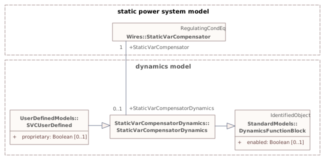
Destination
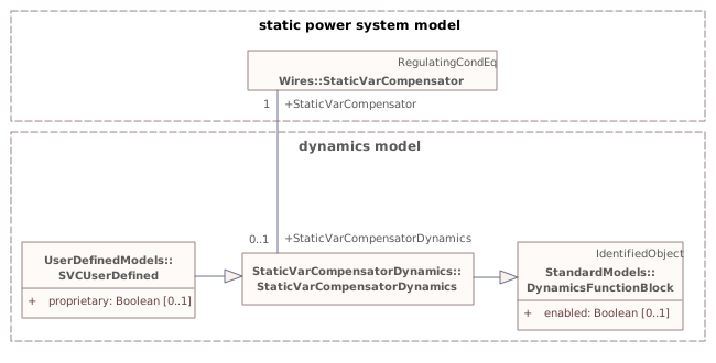
▶InfIEC61970i
{D2DD87AA-AF0C-477c-8E65-69D543D76521}
Package notes
This package and its subpackages contain informative (unstable) elements of the model, expected to evolve a lot or to be removed, and not published as IEC document yet. Some portions of it will be reworked and moved to normative packages as the need arises, and some portions may be removed.
WG13 does not generate documentation for this informative portion of the model.Package metadata — changes
| Baseline | Destination | |
|---|---|---|
| no changes | ||
Tagged values — changes
| Baseline | Destination | |
|---|---|---|
| no changes | ||
Package notes
This package and its subpackages contain informative (unstable) elements of the model, expected to evolve a lot or to be removed, and not published as IEC document yet. Some portions of it will be reworked and moved to normative packages as the need arises, and some portions may be removed.
WG13 does not generate documentation for this informative portion of the model.▶Feederi
{4CD4EBB9-E213-44df-9BD9-20ECAE4160A8}
Package notes
No notes defined in the model.Package metadata — changes
| Baseline | Destination | |
|---|---|---|
| no changes | ||
Tagged values — changes
| Baseline | Destination | |
|---|---|---|
| no changes | ||
Package notes
No notes defined in the model.Changed classes (1)
▶⚙Circuiti
CHANGED{E27D9368-509B-4ea8-9C6C-99D10F5B57E1}
Class notes
No notes defined in the model.Class metadata — changes
| Baseline | Destination | |
|---|---|---|
| no changes | ||
Tagged values — changes
| Baseline | Destination | |
|---|---|---|
| no changes | ||
Class notes
No notes defined in the model.Changed diagrams (1)
▶▦Feederi
CHANGED{54F6543E-23A9-4d57-9CD2-7F210C1716B5}
Diagram notes
No notes defined in the model.Diagram metadata — changes
| Baseline | Destination | |
|---|---|---|
| ModifiedDate | 2019-03-18 20:52:48 | 2020-08-26 11:40:28 |
Diagram notes
No notes defined in the model.▤Metadata
| Baseline | Destination | |
|---|---|---|
| ModifiedDate | 2019-03-18 20:52:48 | 2020-08-26 11:40:28 |
▦Diagram
moved or resizedrestyled
Baseline
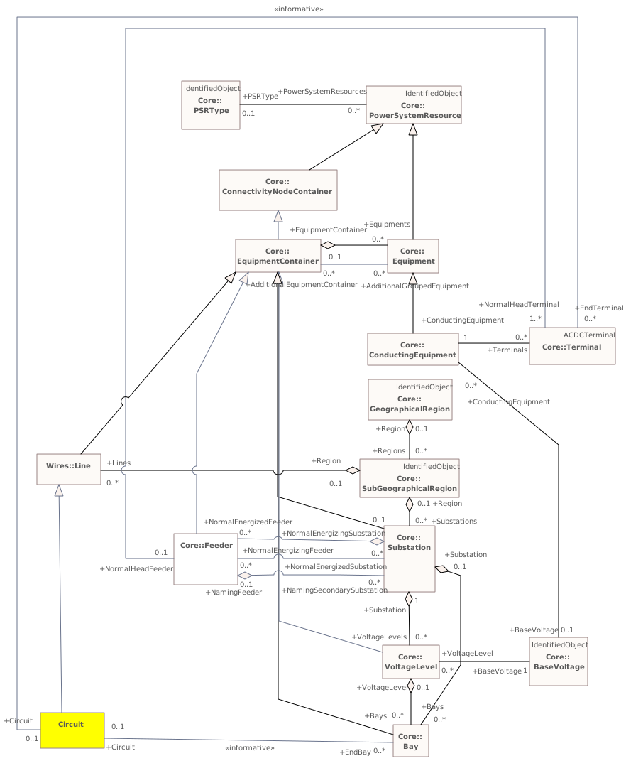
Destination
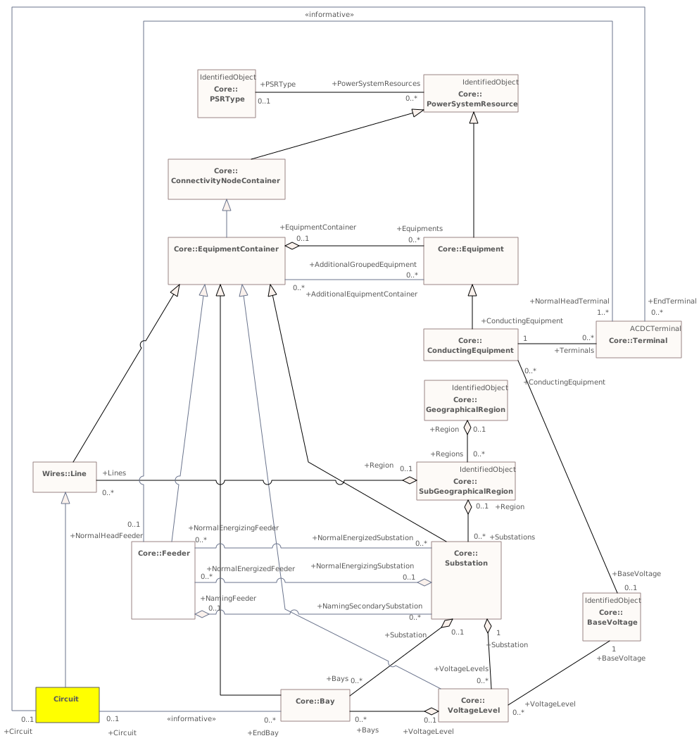
Connectors 26 reroutedhover a connector to outline the elements it joins
rerouted(not in this model) – (not in this model)
rerouted(not in this model) – (not in this model)
rerouted(not in this model) – (not in this model)
rerouted(not in this model) – (not in this model)
rerouted(not in this model) – (not in this model)
rerouted(not in this model) – (not in this model)
rerouted(not in this model) – (not in this model)
rerouted(not in this model) – (not in this model)
rerouted(not in this model) – (not in this model)
rerouted(not in this model) – (not in this model)
rerouted(not in this model) – (not in this model)
rerouted(not in this model) – (not in this model)
rerouted(not in this model) – (not in this model)
rerouted(not in this model) – (not in this model)
rerouted(not in this model) – (not in this model)
rerouted(not in this model) – (not in this model)
rerouted(not in this model) – (not in this model)
rerouted(not in this model) – Line
reroutedCircuit – (not in this model)
reroutedCircuit – (not in this model)
reroutedCircuit – Line
reroutedFeeder – (not in this model)
reroutedFeeder – (not in this model)
reroutedFeeder – (not in this model)
reroutedFeeder – (not in this model)
reroutedFeeder – (not in this model)
Package 'InfIEC61970' has no changes to the 1 diagrams it contains.
Changed classes (1)
▶⚙IEC61970CIMVersioni
CHANGED{990AB50C-5CF8-46d2-B5FF-887BBBD3346F}
Class notes
This is the IEC 61970 CIM version number assigned to this UML model.Class metadata — changes
| Baseline | Destination | |
|---|---|---|
| no changes | ||
Tagged values — changes
| Baseline | Destination | |
|---|---|---|
| no changes | ||
Class notes
This is the IEC 61970 CIM version number assigned to this UML model.≡Attributes
| Attribute | Baseline | Destination | Notes (destination, redlined) | ||||||||||||
|---|---|---|---|---|---|---|---|---|---|---|---|---|---|---|---|
| dateimetadata changed - hovermetadata changed{8DADB97F-283D-40c7-A25A-D75E4C0D8507}show details | Date [0..1] | Date [0..1] | Form is YYYY-MM-DD for example for January 5, 2009 it is 2009-01-05. | ||||||||||||
Attribute notes Form is YYYY-MM-DD for example for January 5, 2009 it is 2009-01-05.Attribute metadata — changes
Tagged values — changes
| |||||||||||||||
| versionimetadata changed - hovermetadata changed{B4E0B1B6-8794-406a-A4C6-CBB395E37A52}show details | String [0..1] | String [0..1] | Form is IEC61970CIMXXvYY where XX is the major CIM package version and the YY is the minor version. For example IEC61970CIM13v18. | ||||||||||||
Attribute notes Form is IEC61970CIMXXvYY where XX is the major CIM package version and the YY is the minor version. For example IEC61970CIM13v18.Attribute metadata — changes
Tagged values — changes
| |||||||||||||||
Package 'IEC61970' has no changes to the 1 diagrams it contains.